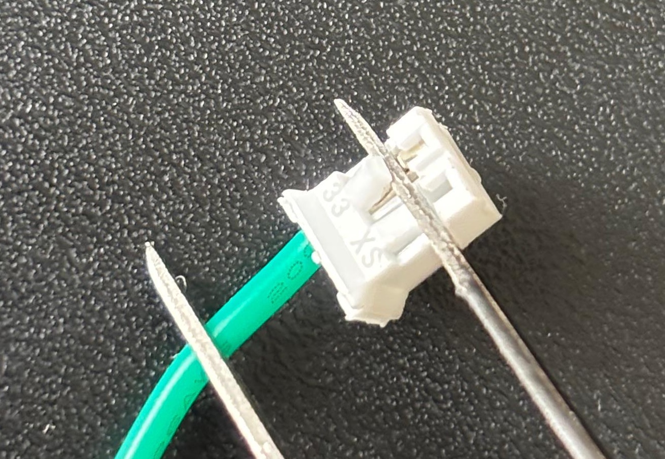
How to Crimp JST PH Connectors With the Engineer PA-09 Tool
A step-by-step guide to crimping JST PH connectors with the Engineer PA-14 and PA-09 tools.
I’m working on a project that uses JST PH connectors and decided to use this as an opportunity to learn how to crimp these connectors. After some research, I settled on two tools made by the Japanese company Engineer : the PA-14 wire stripper and the PA-09 crimping tool .
This post is a tutorial on how to use these tools to crimp JST PH connectors. In addition, I’ll use an AWG 26 cable and a pair of pliers.
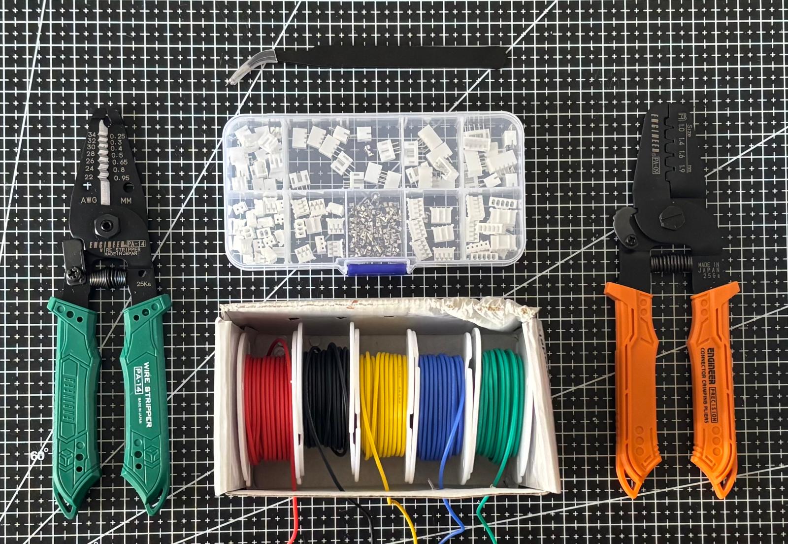
Steps #
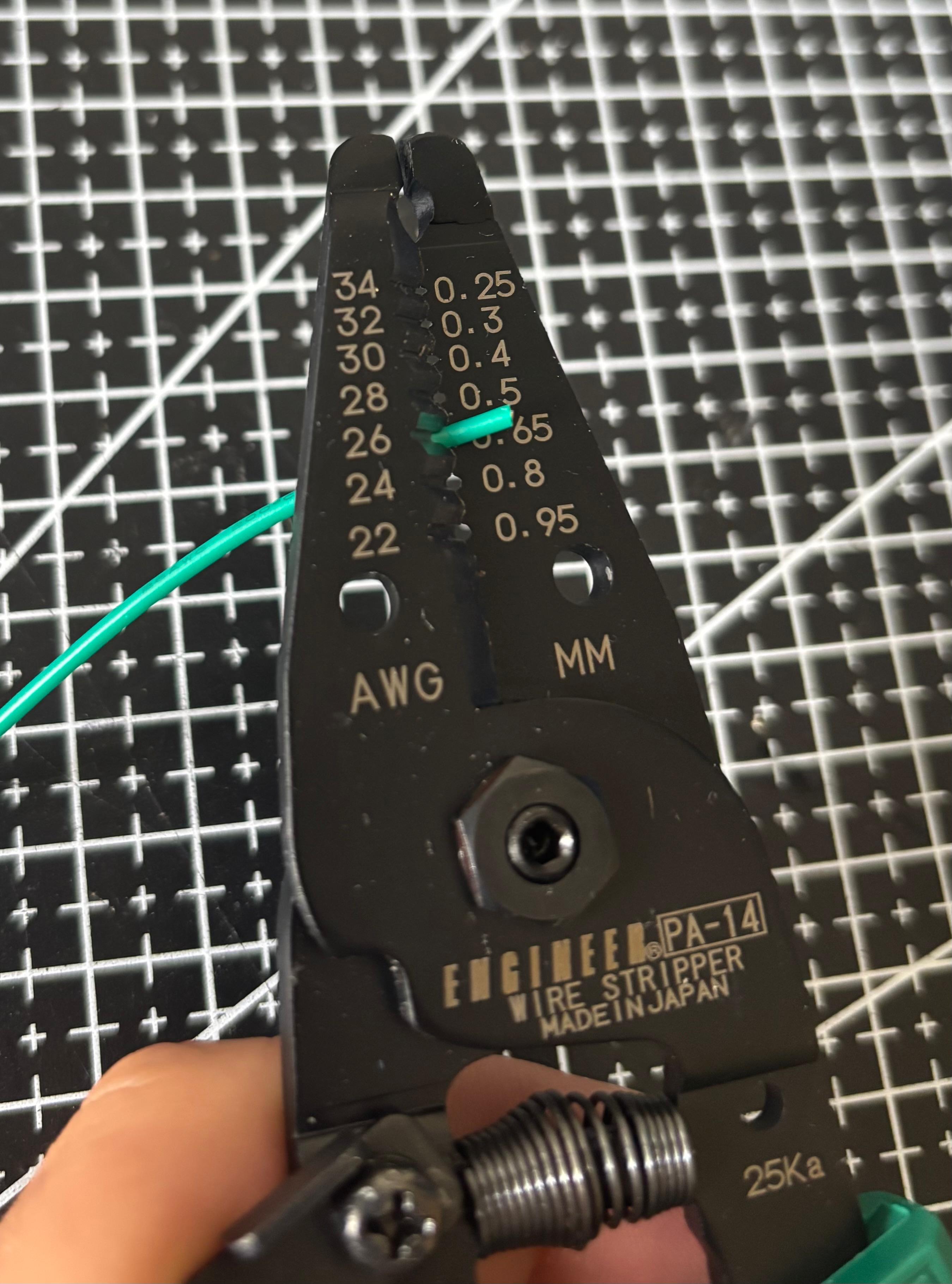
#1 - Use the wire stripper on the width that corresponds to your wire. Make sure to leave some free space on the other end.
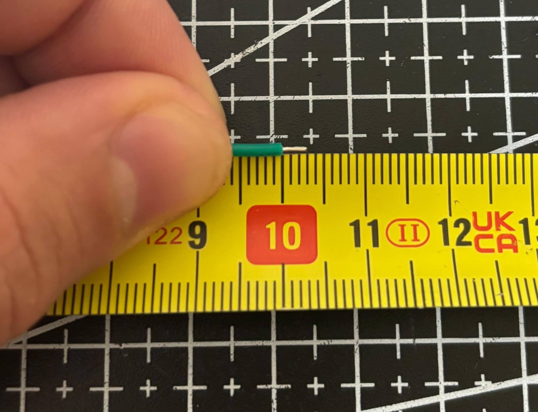
Strip the wire around 3mm in length.
#2 - Twist the stripped wire together to avoid loose strands.
#3 - Use the pair of pliers to decrease the space between the wire barrels.
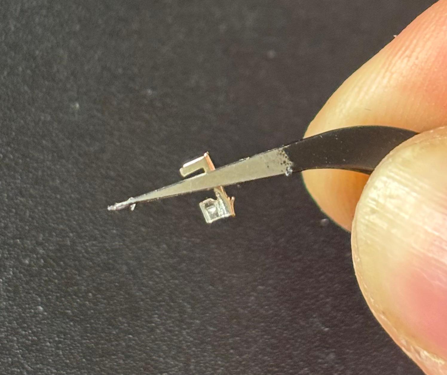
I do this by holding the crimp contact with the pliers, as shown in the picture above, and pushing the tips of the pliers with my other hand.
#4 - Insert the crimp contact into the tool, placing the wire barrels in the 1.4mm slot with the contacts pointing towards the number. Make sure the wire barrels are well centered.
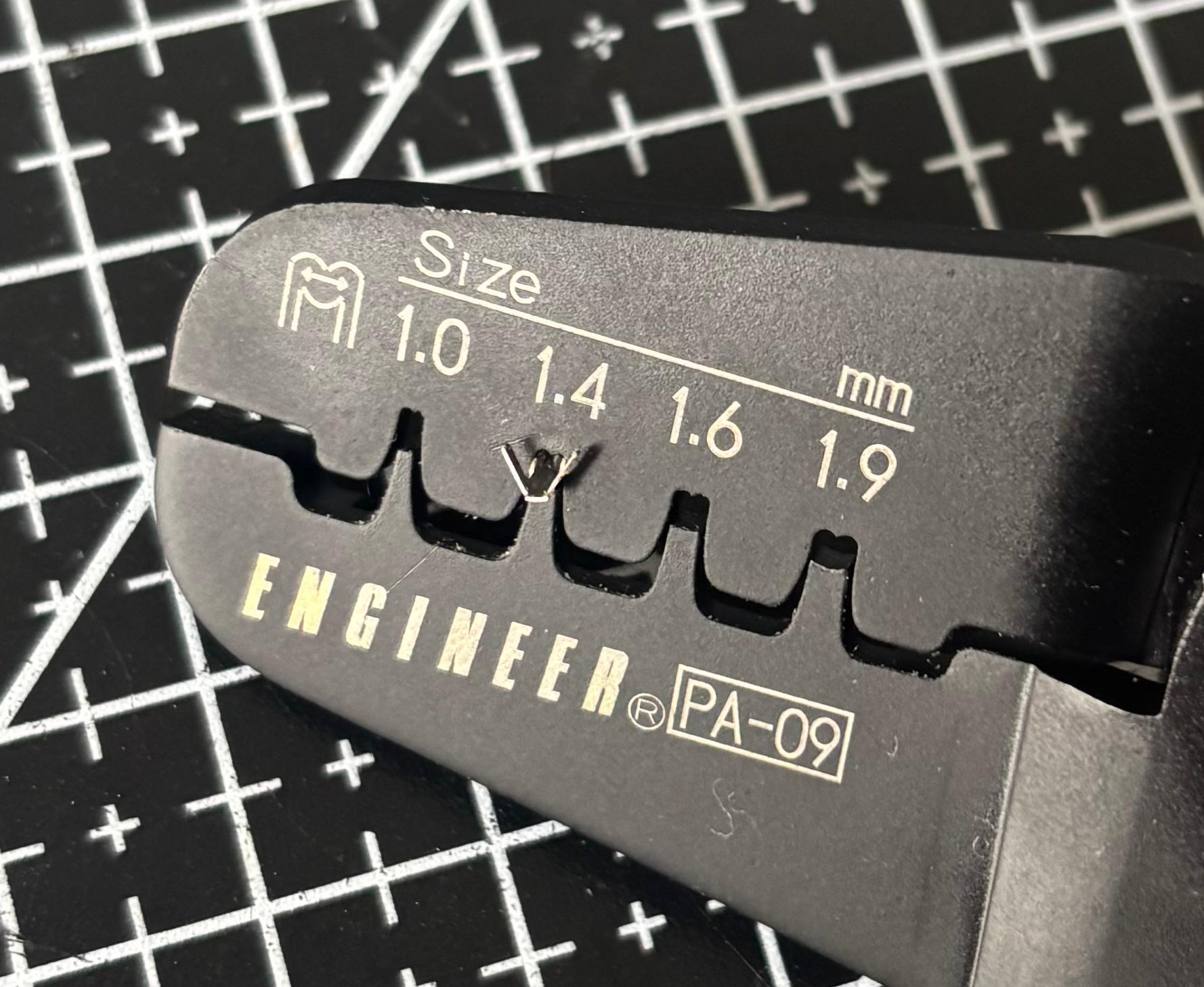
Something that helps is to push the insulation barrels outwards - this will make it easier to insert the cable.
#5 - Insert the cable.
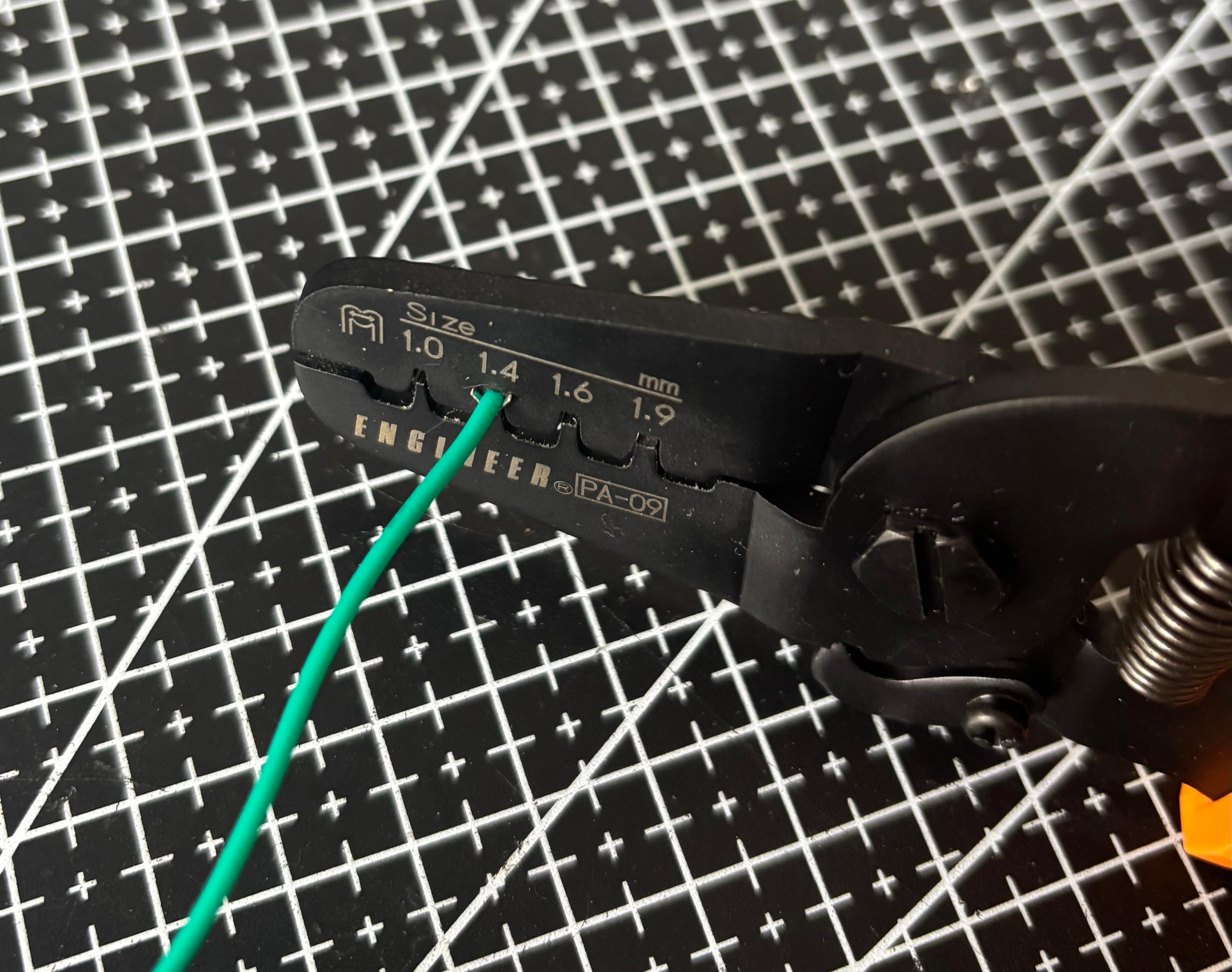
#6 - Push the tool, make sure you feel a click, and check the result. It should look like this:
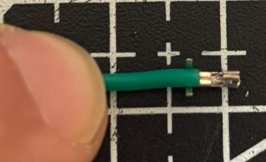
#7 - Next, use any of the tools to push the insulation barrels inwards a bit.
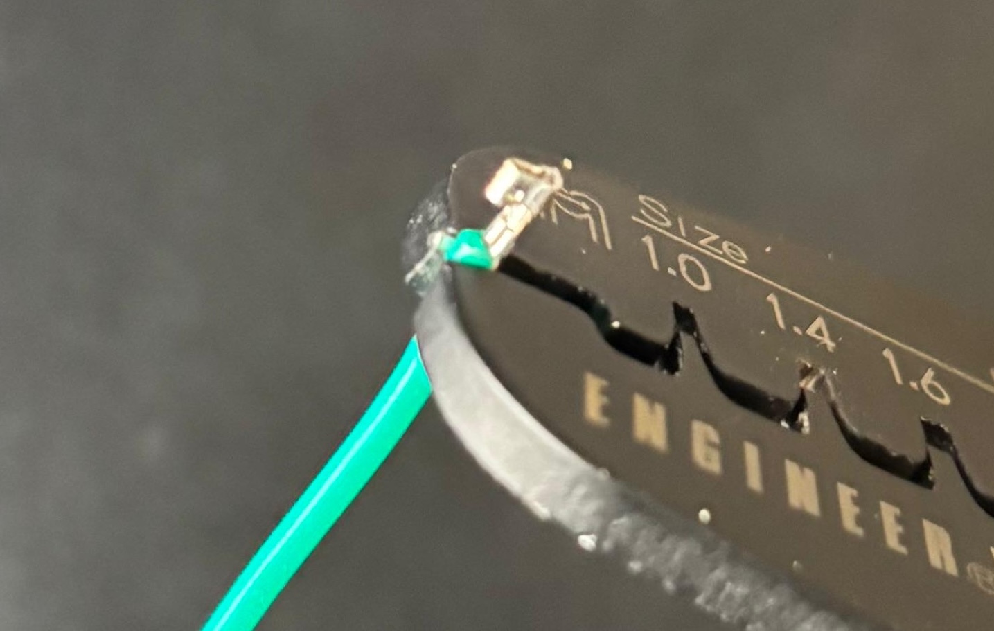
#8 - Insert the crimp contact into the crimping tool, placing the insulation barrels in the 1.9mm slot. Make sure the insulation barrels are well centered.
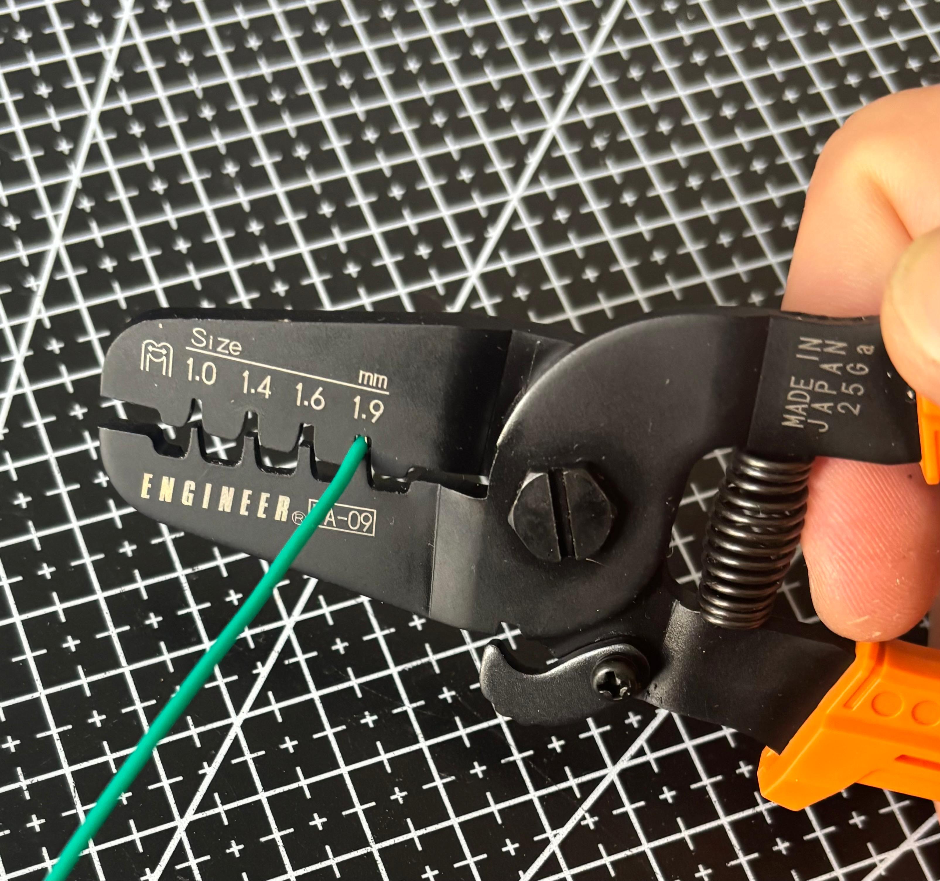
#9 - Push the crimping tool lightly. To get a good quality crimp, make sure the barrels curl inwards towards the center, not to the sides. Pushing lightly makes this easier because you can make adjustments as necessary.
#10 - The final result should look like this:
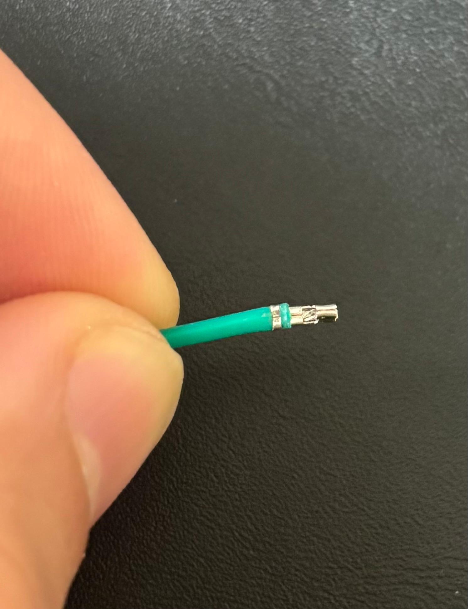
Pull lightly with your fingers to ensure that the crimp contact is well in place.
#11 - Use any of the tools to press the sides of the crimp contact - this ensures that it will enter the connector without problems.
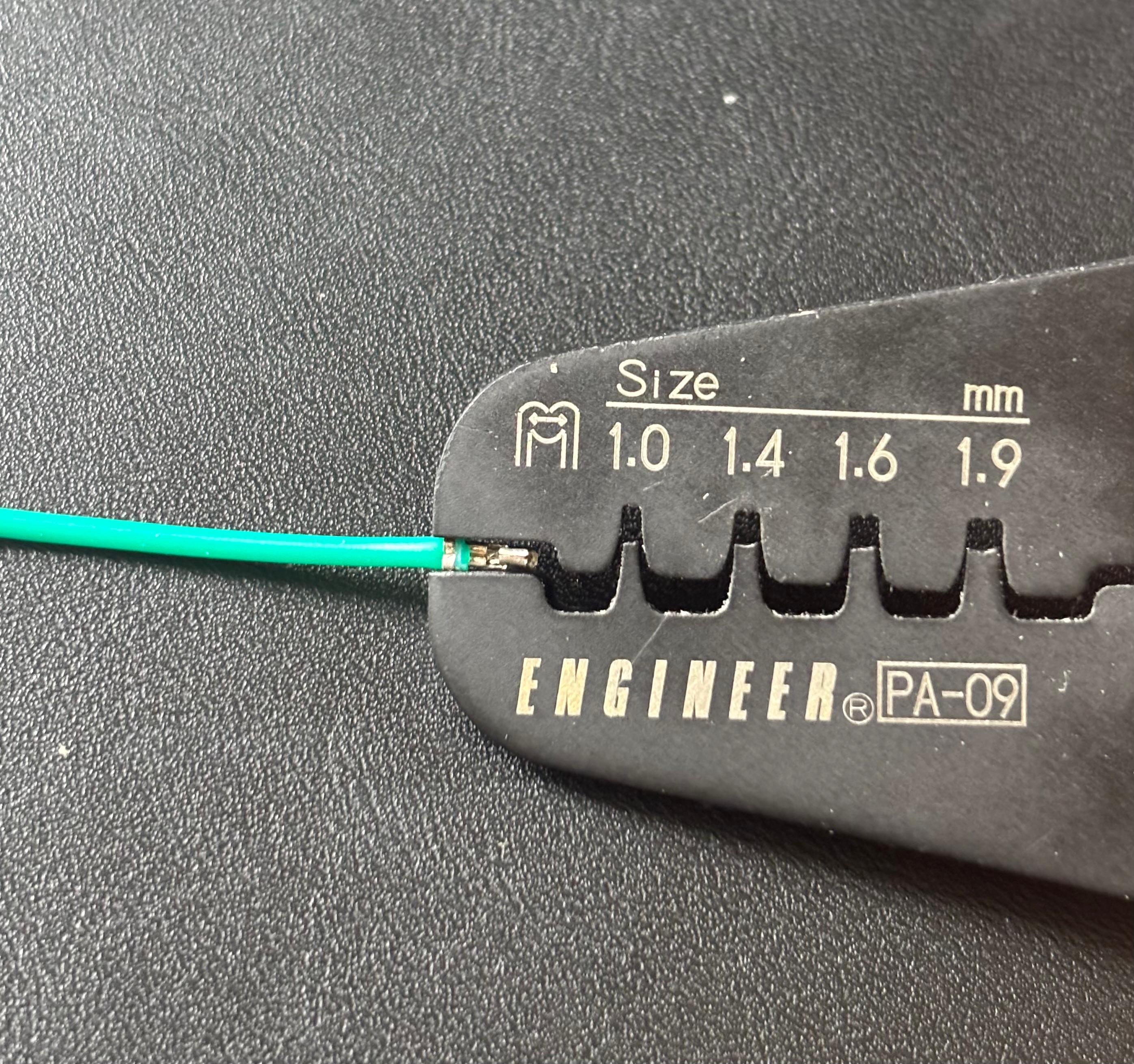
#12 - Now that the cable has been crimped, the final part is to insert it into the connector. This is the orientation you should follow:
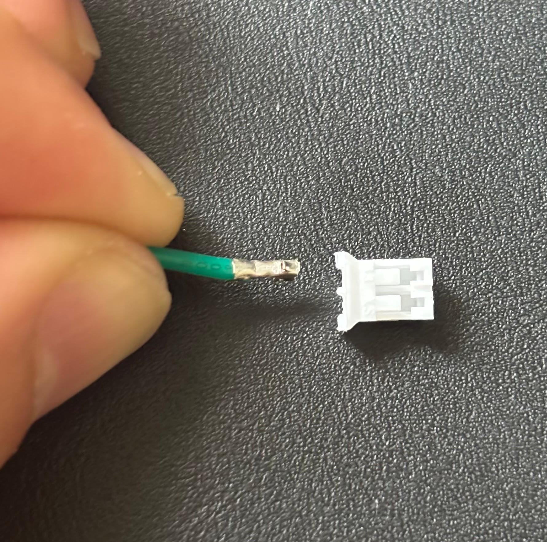
#13 - Insert the cable into the connector. You should hear a click. The crimp should have some wiggle room inside the connector - make sure you can see it. If the cable is completely stuck, then it hasn’t been correctly inserted.
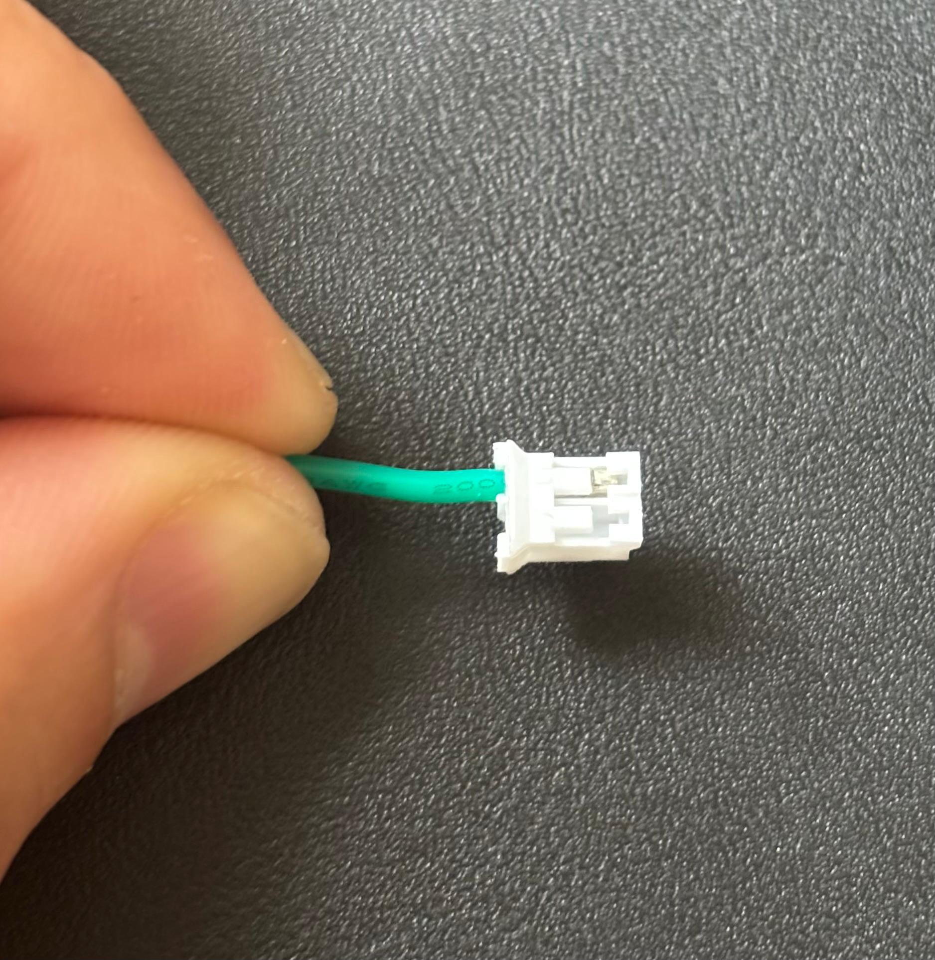
Do a final check by holding the connector firmly and pulling the cable with moderate force.
Extra - You can use the pair of pliers to lift the plastic tab that locks the crimp contact in place if you want to remove the cable from the connector.