Designing and Implementing a Mail Detection System
From coming up with the idea to designing custom PCBs and firmware for Envelope, a LoRa-connected system that detects when mail is delivered to or collected from my mailbox and reports it live to my homelab.
- published
- tags
- #Esp32 #Sensors #Raspberry-Pi #Lora #Mqtt #Design #Embedded #Iot #Altium #Pcb #Soldering #Homelab #Docker #Traefik #Github-Actions #Crimp #Connector #Jst #Wire #Platformio
- categories
- Project Envelope
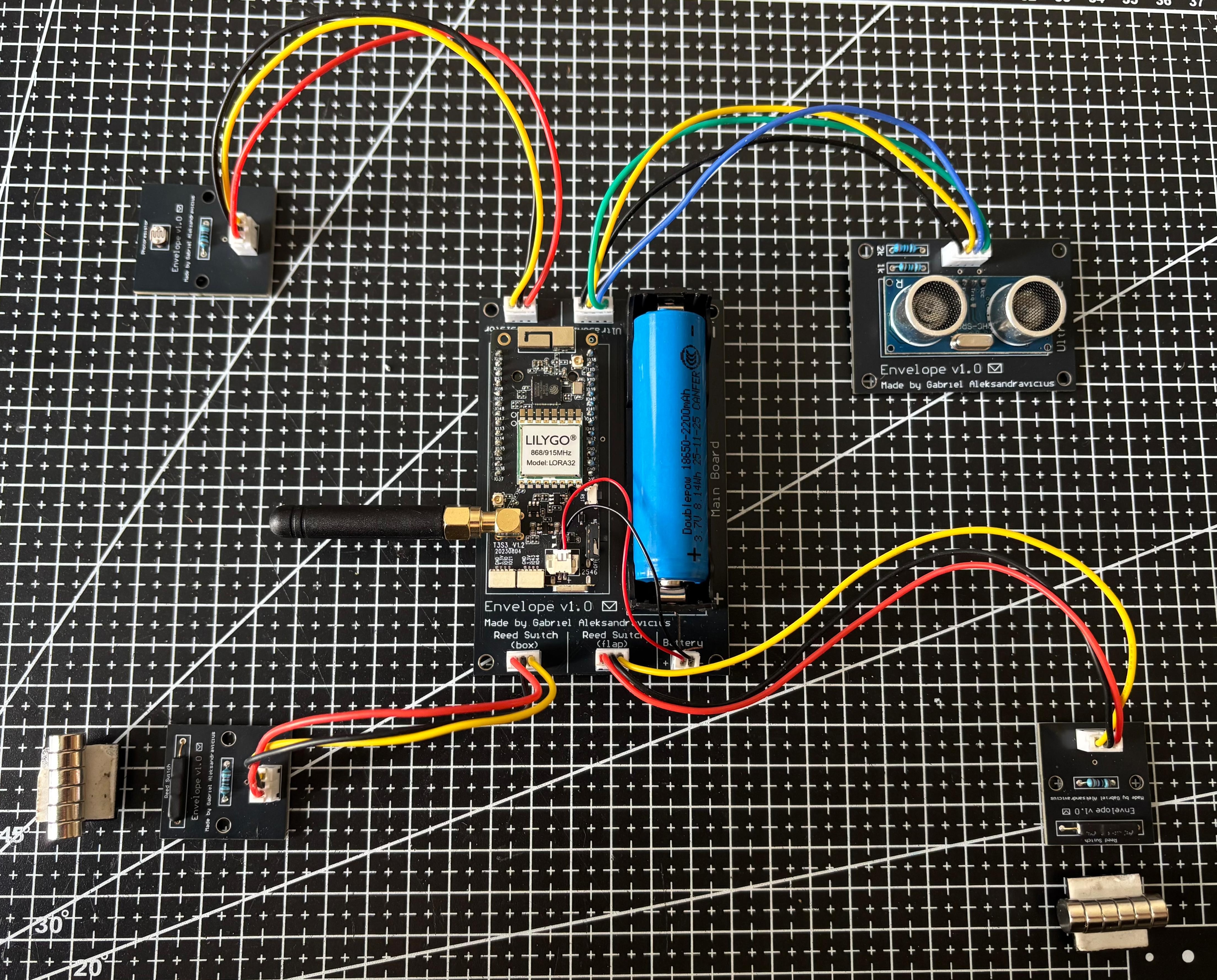
Check this project’s repository on GitHub:
gabrielaleks/envelope
Table of Contents #
- Table of Contents
- What is ‘Envelope’ and how I came up with the idea for it
- Determining the requirements
- Components and tools
- Software
- Hardware
- Deploying the system
- Afterthoughts and next steps
- References
What is ‘Envelope’ and how I came up with the idea for it #
Ever since I moved to Switzerland I started paying more attention to my mailbox. While in Brazil a great deal of bureaucracy can be handled digitally, here I am always waiting for a letter to arrive. More notably, when I first applied for my residence permit I found myself going to my mailbox at least twice a day to see if I had any news from the migration department.
I don’t remember exactly when this idea first crossed my mind but I know that I’ve had it for many months, perhaps more than a year: it would be cool to have an automated way that determines when a new letter has been inserted into my mailbox, when it happened and whether it has been collected.
After getting my
homelab
in good shape, I finally decided to start working on this mail detection system - which I called Envelope.
This blog post will cover the full development cycle I went through to bring this idea to life: from collecting the requirements and determining the components to designing the software, writing it, creating the hardware, soldering everything and deploying the full system.
Determining the requirements #
The idea can be summarized in a few words:
The objective of this project, called
Envelope, is to build a smart detection system that sits inside the mailbox. When something is inserted in it or removed from it, the system detects it and notifies me.
Here’s a picture of my mailbox:
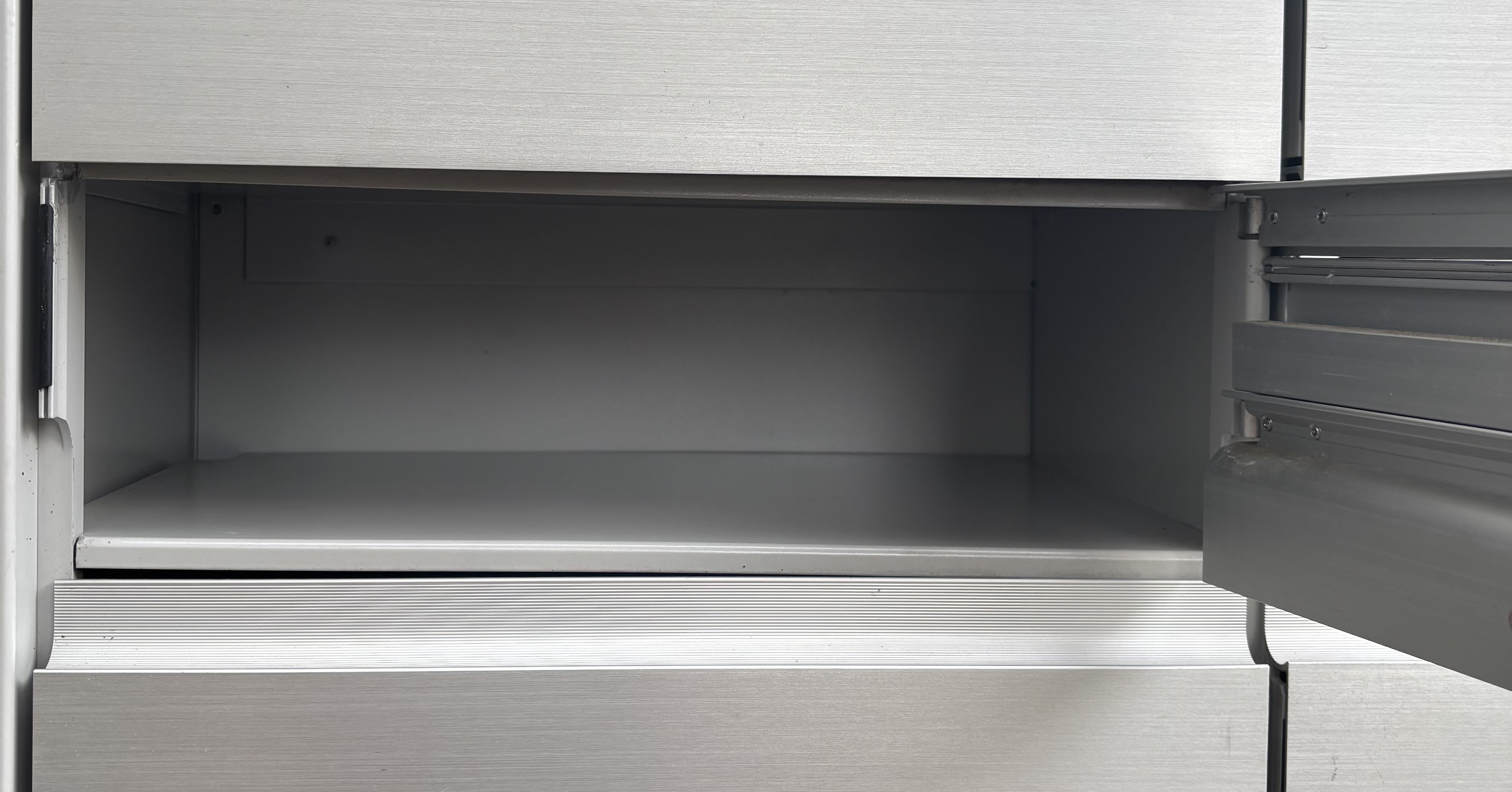
Some info on the mailbox:
- The mailbox is a closed metal box with a flap - a space for letters, envelopes, newspaper, etc. to be inserted - on the top and a door with a hinge on the right.
- When the mailman arrives he pushes the flap, inserts whatever he has for me in the opening, and releases the flap.
- When I want to collect things from the mailbox, I open the door with my key.
- The mailbox sits at approximately 50 meters from my apartment office’s window.
- Internal compartment’s dimensions: 25cm x 40cm x 12cm.
- Flap’s dimensions: 35cm x 3cm.
- Mailbox interior: sealed/dry. Condensation/humidity risk only, no direct water exposure.
- Temperature range: -5C to 35C.
The users of my mailbox are the collectors (in this case, me and my girlfriend) and the deliverers (anyone that only inserts stuff in my mailbox). Together, we all interact with the mailbox in the following ways:
- [deliverer] Opens the flap and inserts things.
- [collector] Opens the flap and checks if there’s anything inside.
- [collector] Opens the box and does nothing (similar to the action above).
- [collector] Opens the box and collects items.
I want my system to tell me whenever any of these happen.
Finally, I have to define what I mean when I say that I want to be >notified< when an event happens. My homelab infrastructure already has Home Assistant, so first I thought about integrating with it. However, since I wanted to have full control over my system, I decided that for the first version I would implement a simple UI containing a live-updating table with the events that happen. This part of the system should get deployed to my homelab infrastructure and should be accessible on https://envelope.kaoshome.dev (if you’re interested in learning how I deploy dockerized systems to my homelab and access them via VPN from anywhere, with HTTPS and a neat URL like that, you’re welcome to read my homelab series ).
With the requirements defined, the next step was to select the components for my system!
Components and tools #
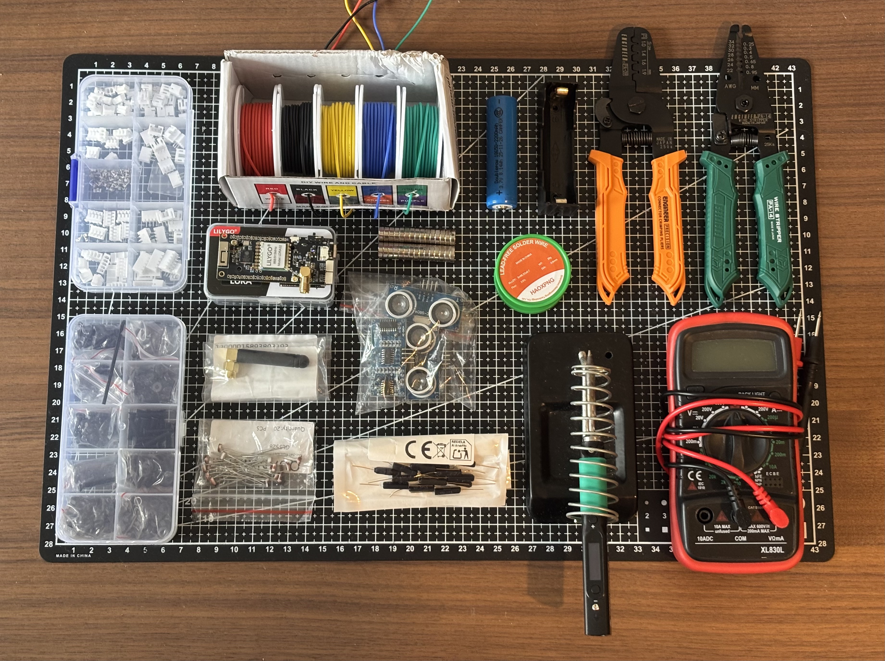
Components and tools used in this project
Microcontroller #
First, the main part: what microcontroller (and devkit) should I use? My first idea was to use a simple ESP-WROOM-32 , since hopefully I would be able to connect to my home router from inside the mailbox. That’s what I tried first but unfortunately the WiFi signal didn’t reach so far, so I had to add a “bridge” - a second ESP32. The first one will sit inside the mailbox with all the sensors and, when an event happens, it will use some sort of long-range communication technology to talk with another ESP32 that lives in my apartment. This 2nd guy will receive a packet containing information about the event and, since it is connected to my home WiFi network, will process it and direct it to appropriate homelab docker service.
I decided to use LoRa as the long-range technology. I will use it for Point-to-Point (P2P) communication, with the transmitter sitting in the mailbox and the receiver in my apartment. Since I am in Europe, I have to use the 868 MHz band.
Since the mailbox has 12cm of internal height, I bought a 5cm right-angle antenna to use with the dev board. The T3-S3 PCB already offers a factory-soldered SMA connector.
Searching for solutions, I found the LilyGo T3S3 dev board , an ESP32 S3-based that offers a LoRa transceiver on the board - in my case, SX1276. It also contains an OLED 0.96" 128x64 display, a microSD slot, battery charging via a JST GH connector. I will use one as the transmitter and one as the receiver.
Sensors #
For the sensors that go inside the mailbox, my initial idea was to use three types of sensors independently:
- Two reed switches (GPS-14B N/C).
- A reed switch is a sensor that detects the presence of a magnetic field, so I also have to buy magnets to use with them.
- One sits next to the flap, the other on the door, each paired with a magnet taped to the corresponding moving part. At rest, the magnet keeps the field present; opening the flap or box pulls the magnet away and breaks it - that’s the event.
- I have two options: normally closed (N/C) and normally open (N/O). I chose N/C because it’s more reliable: at rest (magnet present) the contacts are open and the pin is held HIGH by a pull-up resistor; opening the flap/box closes the switch and pulls the pin LOW. A broken wire just leaves the pin floating HIGH, same as the resting state, not a false trigger. N/O would trigger on any wire fault instead, since a broken wire reads the same as the magnet having left.
- Ultrasonic sensor (HC-SR04). An ultrasonic sensor is used to measure distance. I will tape it to the top of the box, pointing down, and use it to determine if something was inserted or removed.
- Photoresistor (GL5528). A photoresistor is a light sensitive resistor whose resistance decreases as the intensity of light they are exposed to increases.
Connectors #
For the connectors, I decided to go with JST-PH because of their small size while still granting reasonable resistance to accidental disconnection.
Battery + holder #
The T3-S3 has a dedicated onboard battery connector and charge-management circuit built around a single-cell 3.7V Li-ion/LiPo battery. This, and the fact that I have no size pressure to fight, made me choose an 18650 battery. Another option would be to use a bare LiPo pouch, but it is not as standardized, easily swappable, cheap and available.
I bought a holder similar to the BK-18650-PC2 , with two DIP pins at the bottom which makes soldering very easy.
Mounting methods and cabling #
I have to worry about organizing the system inside my mailbox so that mail won’t disturb it. Here, an extra requirement: I don’t own the mailbox, so I can’t drill it or alter it permanently in any way.
For the sensors scattered around the mailbox, I decided to use a double-sided tape, since it holds well to the painted metal interior across the expected temperature range without modifying the mailbox. I chose the 3M VHB double-sided foam tape, 15mm width .
For the cables, I decided to use adhesive-backed cable tie mounts. You tape the pad on the wall, pass a zip tie around it, pass the cables through it and pull the zip tie, securing the cables nicely.
For the T3-S3 dev board, I decided to buy a generic off-the-shelf plastic box, size 127mm x 87mm x 50mm. This served as my reference for the future PCB I would design for the T3-S3.
I also bought an M3 kit box, which comes with washers, nuts and screws (in multiple lengths), all M3-sized. The mounting holes in the PCBs I design and on the battery holder all are M3-sized, so this will come in handy later.
Small stuff #
A few smaller decisions round out the parts list:
- Cable: AWG 26 stranded, silicone-insulated. It gave me more margin for error while learning to crimp for the first time, at no real cost, since the mailbox’s routing isn’t tight enough for AWG 28’s extra flexibility to matter.
- Resistors: a 10K pull-up for each reed switch, a 10K divider for the photoresistor (tuned against the mailbox’s actual light levels), and a 1K/2K divider for the ultrasonic sensor.
- Tools: a breadboard for prototyping, my Pinecil v2 soldering iron (what an amazing tool!), the Engineer PA-14 wire stripper and PA-09 crimping tool (I wrote a separate step-by-step post on using those two - crimping has a learning curve but I got addicted to it), and of course my multimeter, used constantly throughout.
With all of that in hand, I was ready to start working on the project. In the next section I’ll show how I designed and implemented the software.
Software #
In this section, I’ll do my best not to talk about specific lines of code. Instead, I created four diagrams: one for each component (transmitter, receiver, and hub), and one providing an overview of the system. I’ll use them to guide my explanations of what each part of the system is doing. If some part needs further explanation, I’ll cover it in more depth with examples from the code.
Overview #
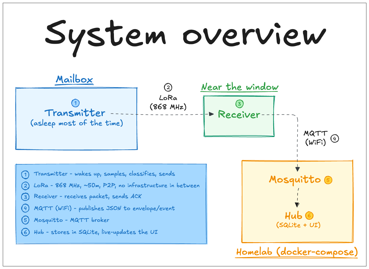
System Overview Diagram
In the diagram above, I identify the major system components:
- Transmitter: Lives in the mailbox and is composed of a T3-S3 and its sensors.
- Receiver: Lives in my apartment, near the window, and is composed of a T3-S3.
- Homelab: There are two relevant docker services I added for this project to run on my homelab setup. First, Mosquitto - an MQTT broker. Second, Hub - which runs SQLite and the webapp that presents the events.
As represented in the diagram, there are 6 steps that happen in the system:
- When an event is detected, the transmitter wakes up from deep sleep, collects samples with the sensors, uses this data to classify the type of event that happened and uses LoRa to send a packet to the receiver.
- LoRa is used as long-range communication technology between the transmitter and receiver. I’m using the 868 MHz band with no extra infrastructure in between the two LoRa radios.
- The receiver will receive the packet sent by the transmitter and send an ACK back.
- Since they are both connected to the same WiFi network, the receiver can reach the homelab. It processes the packet, assembling a JSON from its data, and, using MQTT, publishes it to the
envelope/eventtopic. - On the homelab’s side I am using Mosquitto as the MQTT broker. It persists any data published to its
envelope/eventtopic. - The extreme end of the system is what I am calling “hub”. It is the Node.js + Express app that subscribes to
envelope/event, processes incoming messages, stores them in a SQLite database and displays them in the UI. I’m using SSE (server-sent events) in order to have live updates in the UI.
I’ll cover each component and the transitions between them in depth in the next sections.
Please note that dashed boxes and arrows represent steps and transitions that depend on external I/O - “external” being anything external to the system being analyzed.
Transmitter #
Code:
envelope/transmitter
“Transmitter” is the name I gave to the module that lives its whole life in the mailbox. It contains the ESP32 T3-S3 board, its battery, the two reed switches, one ultrasonic sensor and one photoresistor.
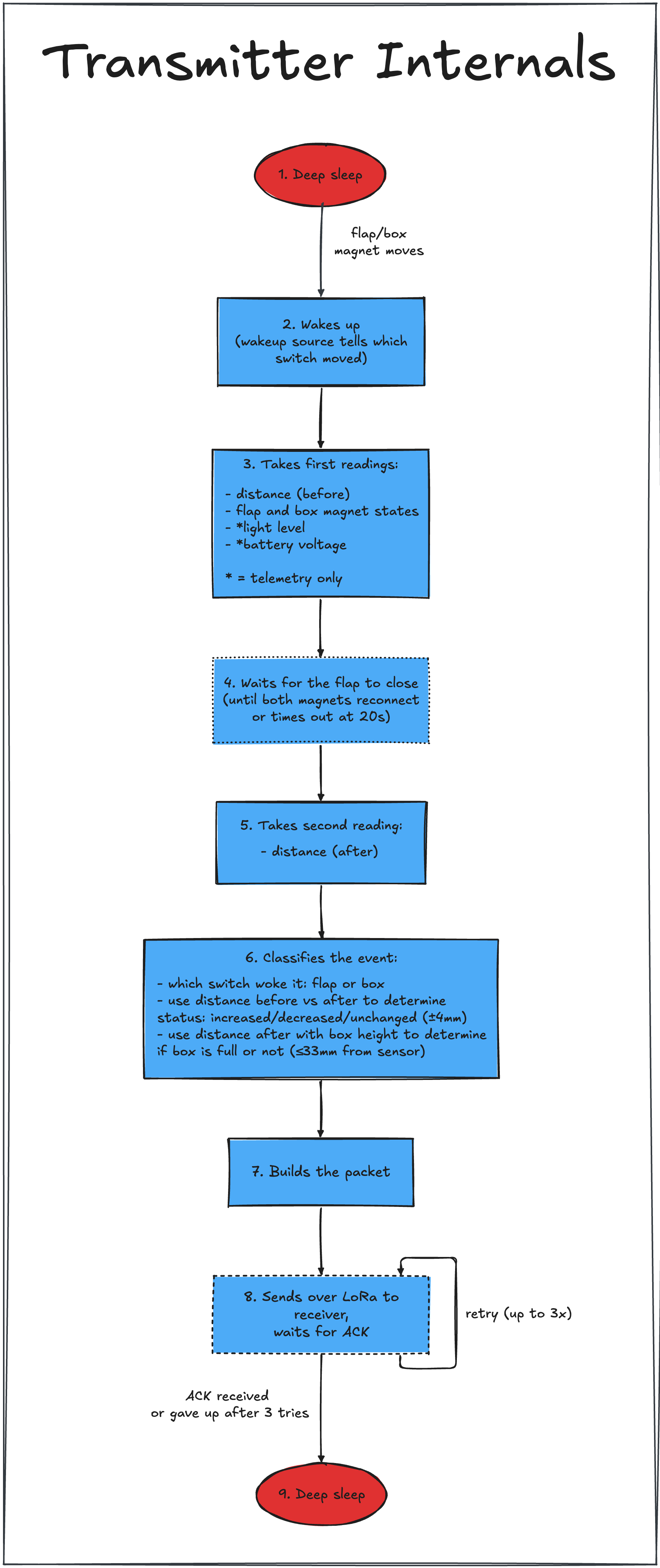
Transmitter Internals Diagram
The diagram above walks through one full wake cycle - from the reed switch trip that wakes the board, through classification, to the retried LoRa send back to the receiver.
#1 - Deep sleep #
The transmitter spends almost all its life in deep sleep. It wakes up only on a physical event - the flap or box magnet moving away from the reed switch. This was my first time designing a system that stays asleep, so first I had to understand how it works and what the best pick for my needs was - light sleep or deep sleep.
First, I decided to use a sleep mode because my system does nothing most of the time, so there’s no need for it to be running in active mode continuously - it would just drain its battery very quickly. Using a sleep mode reduces the power consumption drastically, so I delved into how it works and how to use it.
My biggest references here were two articles from Random Nerd Tutorials - one that explains how deep sleep works and another that explains light sleep.
Light sleep keeps the CPU paused, WiFi off and the RAM data intact. It saves less battery than its alternative - deep sleep. Deep sleep turns off the CPU and WiFi, but the Ultra Low Power (ULP) co-processor can still be used. I can write a program for it so it wakes up the main CPU after an external event happens. Only a specific set of pins can be used by the ULP - RTC_GPIO and touch pins. It has no ADC, so the only wakeup source can be the reed switches. In summary, the relevant distinction between the two is in how quickly each wakes up the system and how much battery it saves.
I decided to start with deep sleep and, if the wakeup was too slow, I’d switch to light sleep. Deep sleep ended up being perfect for me, which I wasn’t expecting since the action of inserting a letter is also super fast!
#2 - Wakes up #
I am using two wakeup sources: GPIO 15 (used by the box’s reed switch) and GPIO 16 (used by the flap’s reed switch). They wake up the board when either pin goes LOW (i.e., the magnet moves away). The pin that got triggered is recorded as the wakeup reason.
If you want to check how I’m handling deep sleep, take a look at the
transmitter’s main.cpp file
.
#3 - Takes first readings #
After the board wakes up, the main part of my transmitter code gets called. Before I explain what happens, let me briefly explain the architecture I have.
In the main.cpp file, I have the setup() and loop() blocks, as in any other Arduino-based application. Since the transmitter doesn’t run a continuous loop - only a specific set of actions when it wakes up - the loop() block is empty, so everything runs inside the setup().
The setup() block starts by defining a watchdog timer - it monitors the system’s operation and recovers from software/hardware faults by restarting the system if it becomes unresponsive. It then defines all the rules for my deep sleep setup and, when either pin goes low, it calls Manager::run().
The transmitter has 5 classes: one for each sensor (to initialize them and get measurements), one for the event classification - EventClassifier - and one to orchestrate the operations. The latter one is Manager. Its run() method will:
- initialize the sensors, the display and LoRa,
- get the first set of measurements from every sensor,
- wait for the event to finish (i.e. for the flap or box to be closed),
- get a new measurement from the ultrasonic sensor,
- use the collected data to classify the type of event (calling
EventClassifier::classifyEvent()), - assemble a packet to send to the receiver,
- send the packet via LoRa.
After that, the transmitter goes back to deep sleep.
With the inner workings of Manager already explained, let me come back to step 3 in the diagram. The first readings taken by the transmitter include:
- distance: the >before< represents the distance from the top of the box to its bottom, right at the start of the event.
- flap and box magnet states: even though I know which reed switch was responsible for the event, I read from both for debug purposes.
- light level: direct reading from the photoresistor
- battery level: I read from it here not only for debug reasons but also because I want the UI to show a badge when the battery level goes under a threshold determined by me, which alerts me to recharge the battery.
#4 - Waits for the magnets to reconnect #
The code then waits for both magnets to reconnect. If it takes too long (more than MAX_CLOSE_WAIT_MS), it times out and the rest of the operation continues. This timeout exists mainly as a power safeguard - if the flap gets stuck open, the door is left open, or the magnets accidentally drift away from the reliable range in which the reed switches operate, then the transmitter would be left awake forever.
#5 - Takes second reading #
After coming back from the wait loop, a second reading is made with the ultrasonic sensor. No other sensor gets called.
#6 - Classifies the event #
This is where EventClassifier::classifyEvent() gets called into action. It uses the distance data (before and after) and the reed switch that caused the event to determine which event happened and what the fill-change was (i.e. if something was added/removed or nothing changed) - the box takes precedence if both switches wake the device at once. It also uses constants defined in the transmitter’s config file to determine if the box is full or not. For this, I had to consider the height of the box and the height of the ultrasonic module, and set an arbitrary value to represent a >full< state.
#7 - Builds packet #
You can check the packet format here:
envelope/shared/packet.h
. Apart from the collected data, it also contains:
- A sequence number
- A magic word known by the transmitter and receiver to avoid RF noise:
#define PACKET_MAGIC 0xAB12
I added this because sometimes the receiver would pick up a random signal and interpret it as an incoming packet from the transmitter.
One thing worth noting: only the >after< distance reading makes it into the packet, and from there into the hub. The >before< one only exists long enough to compute the fill-change locally, then gets discarded.
#8 - Sends packet over LoRa to receiver #
The final thing that Manager::run() does is send the assembled packet via LoRa to the receiver.
LoRaRadio.cpp
is one class used symmetrically by both sides: transmitter and receiver each instantiate their own SX1276 radio and call the same init(). What actually makes them able to talk to each other, though, comes down to a few things defined as radio parameters inside that init(): frequency, bandwidth, spreading factor, coding rate, sync word, preamble length and CRC. The LoRa demodulation only works if transmitter and receiver agree on all of these, which is why I share them in
envelope/shared/common_config.h
.
If the send fails, I log the error and break out of the loop. If it is successful, the transmitter immediately flips to listening for an ACK. This is the ACK retry loop, one attempt at a time:
- Send fails: logged, loop breaks immediately, no more attempts this wake.
- Send succeeds: the transmitter immediately flips to listening for an ACK.
- ACK received: loop ends, this is the success path.
- Timeout: the packet may never have reached the receiver, or the ACK got lost coming back. Logged, retried on the next attempt.
- Any other receive error: treated as a send failure, bumps
errorCount.
errorCountpersists across wake cycles (RTC_DATA_ATTR). Once it exceedsLORA_ERROR_REINIT_THRESHOLD, the radio is re-inited and the counter resets, so repeated hard failures across separate events force recovery instead of retrying blindly forever.
#9 - Goes back to deep sleep #
The system then goes back to deep sleep. Excluding the wait for the flap/box to close, the rest of the wake cycle takes well under a second (assuming no errors were thrown and no retries were needed).
Receiver #
Code:
envelope/receiver
“Receiver” is just the ESP32 T3-S3 board that lives in my apartment, near the homelab. It listens for LoRa packets from the transmitter at the mailbox and forwards parsed events to the home MQTT broker. It is always powered and always listening (i.e. it is not in light/deep sleep), talking to the transmitter over LoRa and to the MQTT broker over WiFi, publishing JSON to topic envelope/event.
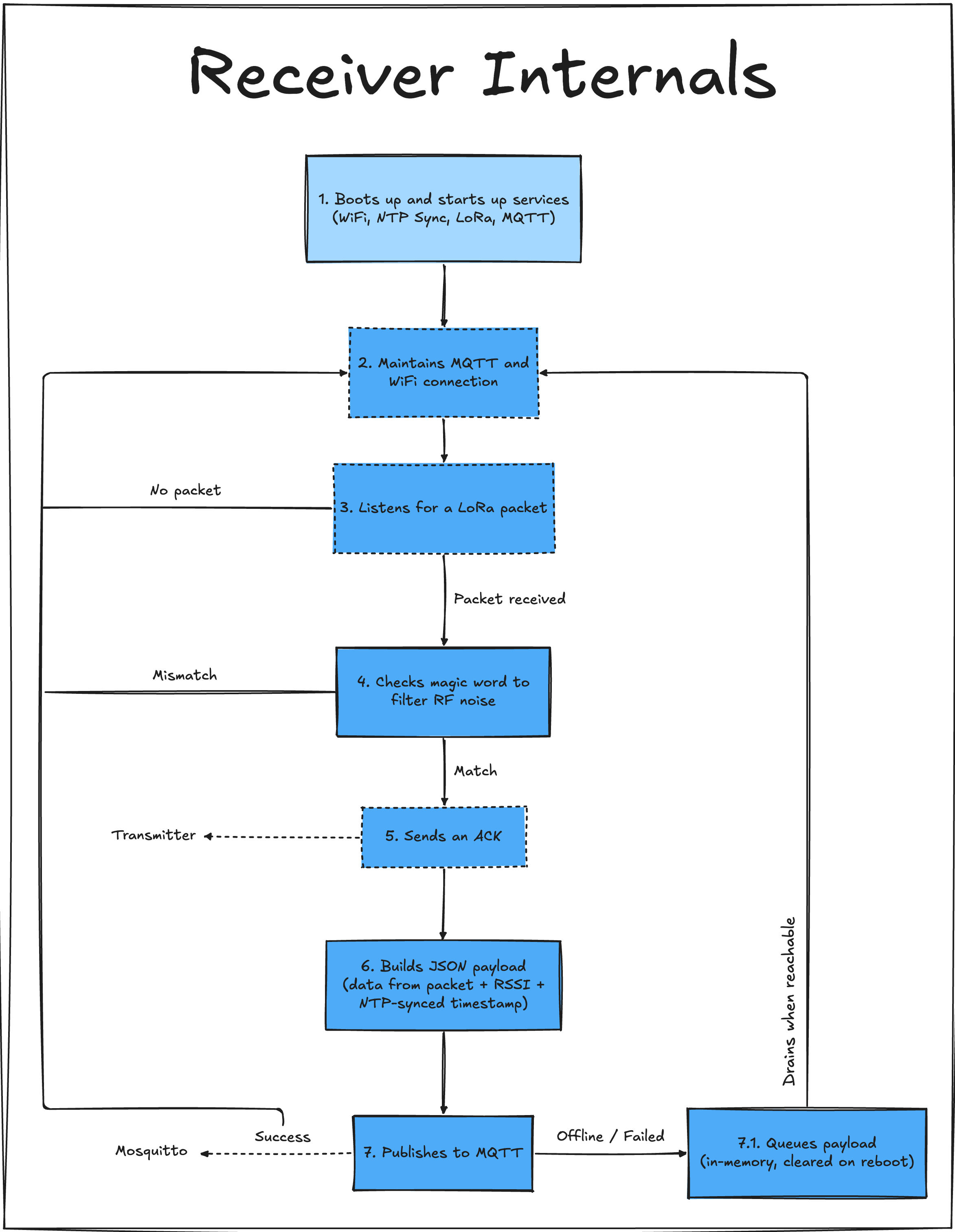
Receiver Internals Diagram
#1. Boots up and starts up services #
Unlike the transmitter, the receiver defines both the setup() and loop(). The following things are done once, at startup, in the setup() block:
- Initializes the watchdog
- Initializes the display
- Initializes the LoRa radio
- Connects to WiFi
- Syncs time using NTP (Network Time Protocol)
- Connects to the MQTT broker
#2. Maintains MQTT and WiFi connection #
While nothing happens, the system just services the MQTT client and remains connected to the WiFi connection.
#3. Listens for a LoRa packet #
The LoRa radio on the receiver’s side listens for an incoming packet.
#4. Checks magic word #
If a packet is received, the first thing that gets checked is the magic word to make sure that it’s not just noise.
#5. Sends an ACK #
Right after identifying the packet as something that got sent from the transmitter, the receiver returns an ACK.
#6. Builds JSON payload #
A JSON payload is built by PacketSerializer::serialize(), using the content of the packet, the RSSI and the timestamp of the event.
#7. Publishes to MQTT #
If the WiFi connection is established, the JSON payload gets published to the envelope/event topic. Publishing it without errors is the success path.
#7.1. Queues payload in-memory #
If either the WiFi connection is unavailable or the publishing fails, the payload gets pushed to a queue. This queue will be drained whenever WiFi is available again.
Hub #
Code:
envelope/hub
Hub is the home-side service. It subscribes to the MQTT topic the receiver publishes to (envelope/event), stores every event in SQLite and serves a live-updating HTML table at port 3000.
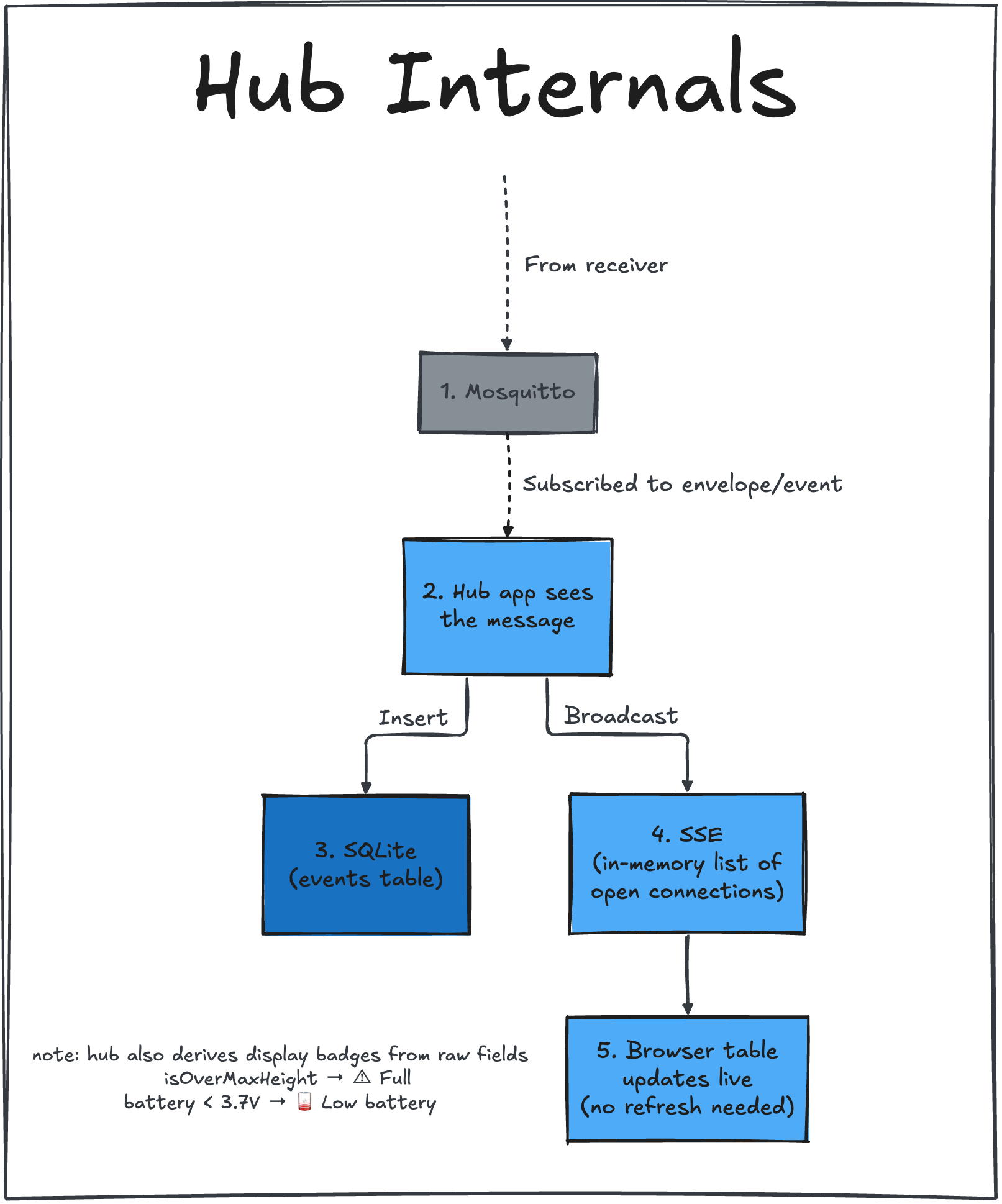
Hub Internals Diagram
#1. Mosquitto #
Mosquitto is the MQTT broker used by Envelope. It runs on port 1883, has auth and rejects anonymous connections. It also persists and logs to a folder that gets bind-mounted into the container.
#2. Hub app sees the message #
The hub app uses an MQTT client and connects to Mosquitto, subscribing to envelope/event. On each message it:
- Parses the JSON
- Inserts a row into SQLite (
/db/envelope.db, bind-mounted fromhub/db) - Pushes the event to any open browser tab over SSE
It serves GET / (the HTML table) and GET /events (the SSE stream) on port 3000.
#3. SQLite #
I decided to use SQLite since this database is super simple. It is initialized by the app itself and contains only a table for the events.
#4. SSE and #5. Browser table updates live #
I keep an in-memory list of open connections. I did this to make the experience of using the app simple: you just open a tab and leave it open, no need to refresh to see if an event happened.
That covers new events showing up live, though. When you first open the page (or refresh it), the server queries SQLite directly for the existing rows and renders the full table. SSE just takes over from there to push whatever comes in after.
Shared #
Code:
envelope/shared
“Shared” is not a specific module, but a folder in which I created the classes shared by transmitter and receiver. It contains Display.h/.cpp, LoRaRadio.h/.cpp and Log.h/.cpp, all of which are used extensively by the two systems.
It also contains shared header files, such as packet.h (contains the format of the packets transmitted/received over LoRa), common_config.h (contains log constants and display and LoRa pins) and secrets.h (contains the WiFi and MQTT config).
Finally, I also stored code examples I used to quickly validate my system under
envelope/shared/examples
. For example, it has code that only tests transmitting a packet, receiving a packet, using the reed switch etc. This was an easy way of doing sanity checks when things stopped working.
Hardware #
Docs:
envelope/hardware
Validating the system on the bench with breadboards #
By the time I started working on the code, all of the components I bought had already arrived. This meant that I could validate my system on the breadboard as I developed it. Here’s a representation of the circuit on Fritzing:
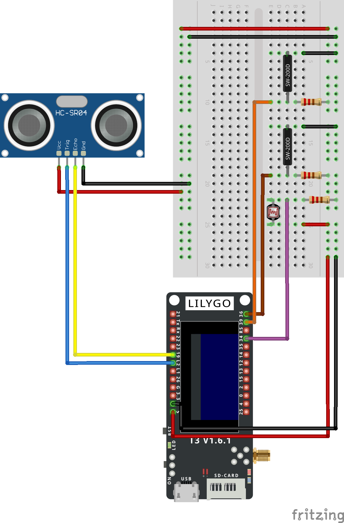
Breadboard circuit on Fritzing
Also check the circuit on a real breadboard in a picture I took while testing sending and receiving ACKs:
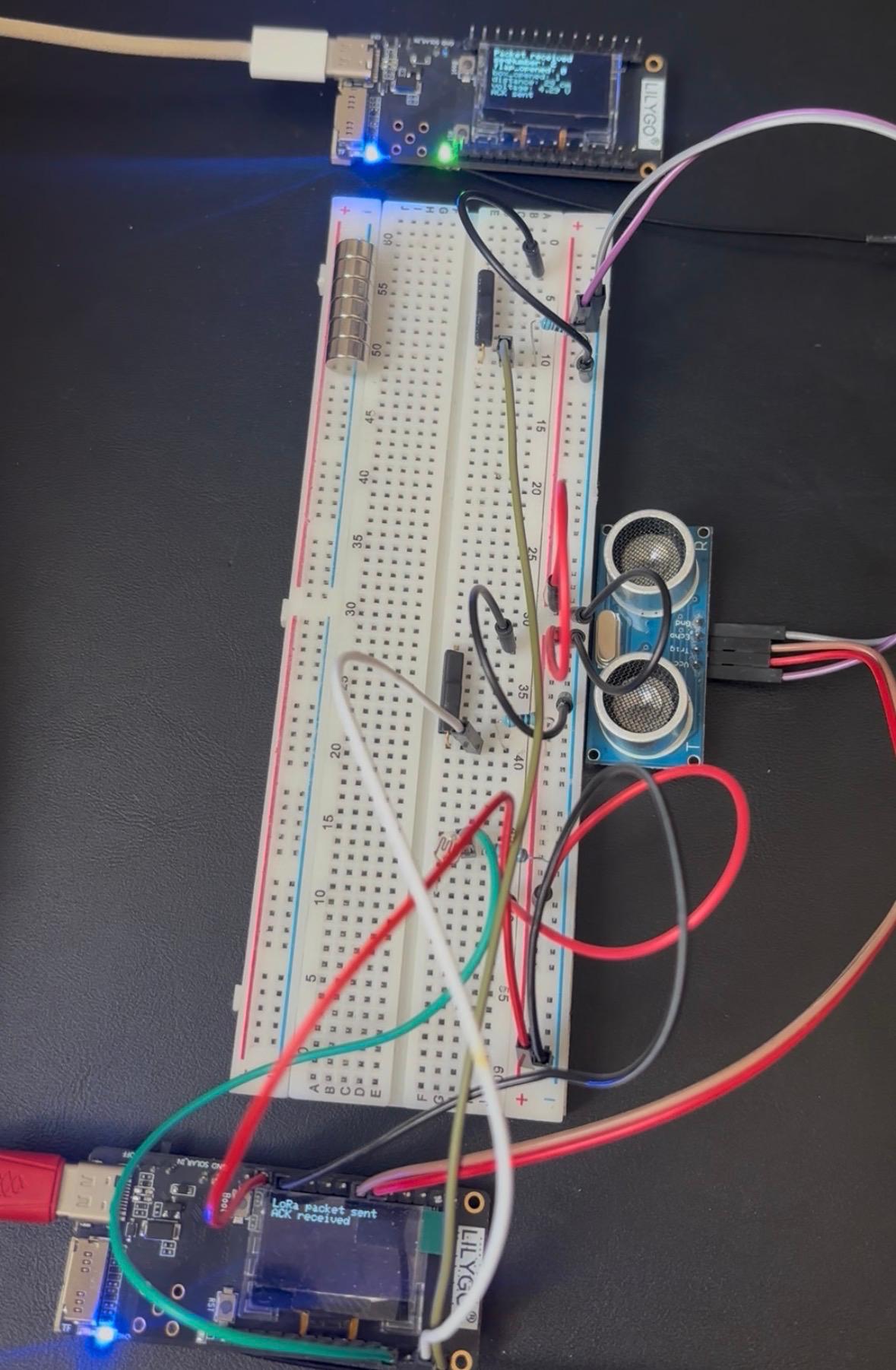
Real breadboard circuit
Once I reached a rather stable version of the firmware and the hardware had been validated, I decided that I wanted to give a real professional look to this project so I started working on PCBs for the system. This would not only make everything look shiny and pretty but also make the deployed system a lot more stable than other options. Putting the breadboard in the mailbox would be a disaster; another option would be to use those double-sided circuit boards for soldering projects (like this ), which I started testing with but also didn’t like the result.
Designing my PCBs on Altium #
I used to work a lot with Altium in the past (it’s been 6 years already!), so I was very excited to come back to it.
I used this as an opportunity to see how Claude can help in a hardware project, and it was great. First, one thing that I did was create a bunch of Architecture Decision Records (ADRs) to help me decide on what to choose for the hardware when faced with multiple options. I created a template for the ADR, chatted with Claude about what I was looking for and what options I thought I had, and asked it to write me an ADR so I could take a decision. It would formalize the ideas I had, use the options I suggested, add more if there were any, and wait for my conclusion. This was an awesome way of progressing, making decisions and writing documentation. For example, ADR-001 is about the connector family I would use for the project. It presents each option, gives its pros and cons, shows what was decided and what the consequences will be. You can see the full list of ADRs I wrote here:
envelope/hardware/adrs
.
I also created a full list of hardware requirements. It contains environmental, electrical and mechanical requirements. You can check it here:
envelope/hardware/requirements.md
.
I also wrote the main design rules I would follow into a file. It contained not only fab-capability rules that are also used by the fabricator I used (JLCPCB) but also standards I defined, such as the connector pin order, the through-hole pad sizes and the trace widths I used for power and signal lines.
Finally, I created one markdown file for each hardware module. It was natural to define 4 modules: main board, photoresistor, reed switch and ultrasonic.
I’ll briefly present each in the next sections.
Main board #
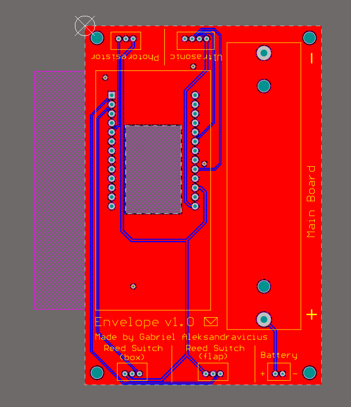
Altium - Main Board
Elements:
- T3-S3: The dev board won’t be soldered directly to the board but socketed via row sockets (13 pins on each side).
- Holder for an 18650 battery cell.
- Antenna (connected to the T3-S3 but I had to account for its size since it protrudes from the board).
- 4x JST PH connectors, one per sensor module: 2x 3-pin (reed switch), 1x 3-pin (photoresistor), 1x 4-pin (ultrasonic).
- The T3-S3 has no bare VIN/BAT pad - its onboard battery input is a small pre-mounted 1.25mm-pitch SMD connector. To connect to it, I added a 2-pin JST PH connector.
- Two power rails: 3.3V (used by the reed switch and photoresistor) and 5V (used by the ultrasonic module).
I added a cutout under the socketed T3-S3, exposing its onboard OLED display so it stays visible for debugging.
I designed this board to have a size of 64.95mm x 98.5mm. I added 4x M3 mounting holes, one on each corner, so if I decide in the future to mount it on a structure instead of just leaving it loose inside the enclosure, I can.
Photoresistor #
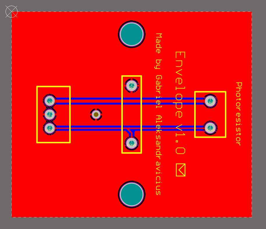
Altium - Photoresistor
Elements:
- Photoresistor (GL5528).
- 10K divider resistor.
- 3-pin JST PH connector.
The divider resistor stays on this module (not on the main board) to keep the signal reaching the main board already conditioned rather than exposing the raw high-impedance divider junction to the cable run.
The final size of this module is 35mm x 30mm. I added 2x M3 mounting holes, positioned on two sides. This module can be taped anywhere.
Reed switch #
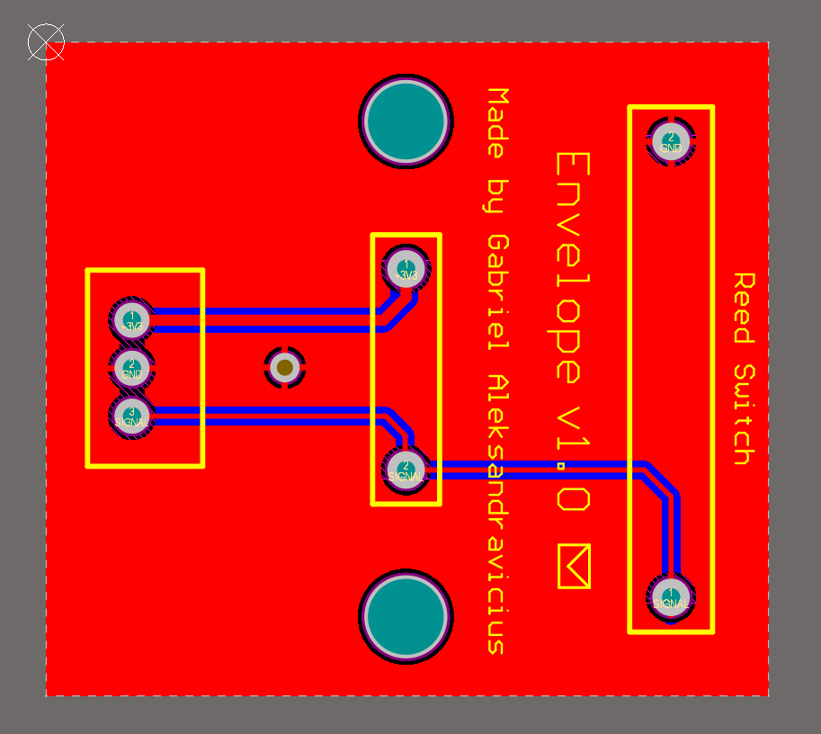
Altium - Reed Switch
Elements:
- Reed Switch (N/C), 2mm x 14mm.
- 10K resistor.
- 3-pin JST PH connector.
This is the only PCB that will be used twice: one for the flap switch and one for the box switch. The PCBs are identical - the only difference is which connector on the main board they connect to.
The magnet is not part of this module. It will be taped to the moving part of the mailbox. The reed switch module itself is mounted stationary, right next to where the magnet sits. The gap distance and magnet orientation matter a lot (!) for reliable switching. I empirically tested this, and the actual operate distance with the real 6x stacked magnet configuration I am using ranges from 2 to 3 cm. Knowing this, my target was to set them 2.5cm apart when taping them to the mailbox.
The final size of this module is 30mm x 27.2mm. I added 2x M3 mounting holes, positioned on two sides.
Ultrasonic #
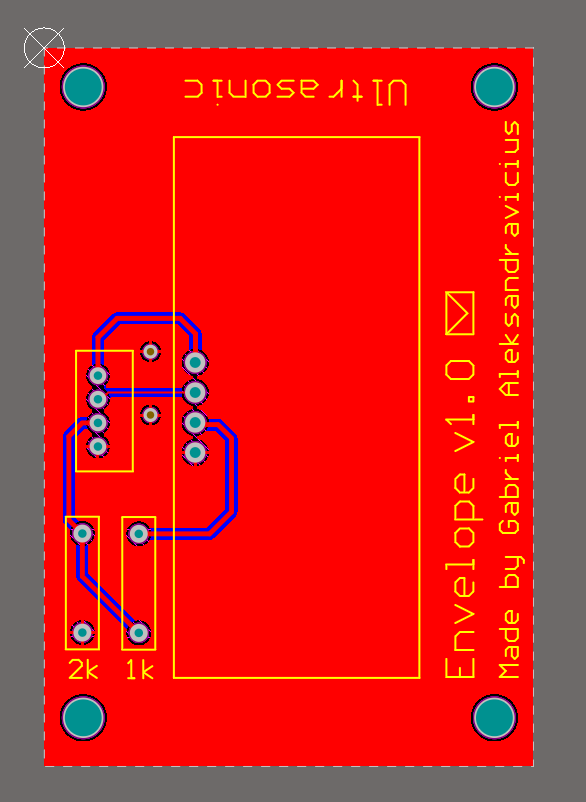
Altium - Ultrasonic
Elements:
- Ultrasonic sensor (HC-SR04).
- Echo voltage divider: 1kΩ + 2kΩ resistors, steps the HC-SR04’s 5V echo signal down to a level safe for the ESP32-S3 GPIO.
- 4-pin JST PH connector.
The HC-SR04 needs 5V VCC to trigger reliably, unlike the other three sensor modules, which run natively at 3.3V, one of the two power rails. Its Echo output swings to whatever it’s powered from, so at 5V it would exceed the ESP32-S3 GPIO’s safe input range (~3.6V absolute max) if wired directly, risking damage to the pin from repeated exposure every reading cycle. Trigger needs no adjustment: the ESP32-S3 driving 3.3V into Trigger already reads as a valid logic-high on the HC-SR04 side. Echo gets a resistor divider before it reaches the connector, so the cable itself only ever carries an already-safe signal. Logic:
- R1 = 1kΩ, between the HC-SR04’s Echo pin and the divider output node.
- R2 = 2kΩ, between the output node and GND.
- Output feeds the connector’s echo pin: 5V x 2000/(1000+2000) = 3.33V, safely within the GPIO’s readable range.
The final size of this module is 41.4mm x 60.8mm. I added 4x M3 mounting holes, one on each corner.
This module will be taped at the center of the ceiling of the mailbox, pointing down.
Multiboard view #
I used Altium’s multiboard view to see how the PCBs would look together.
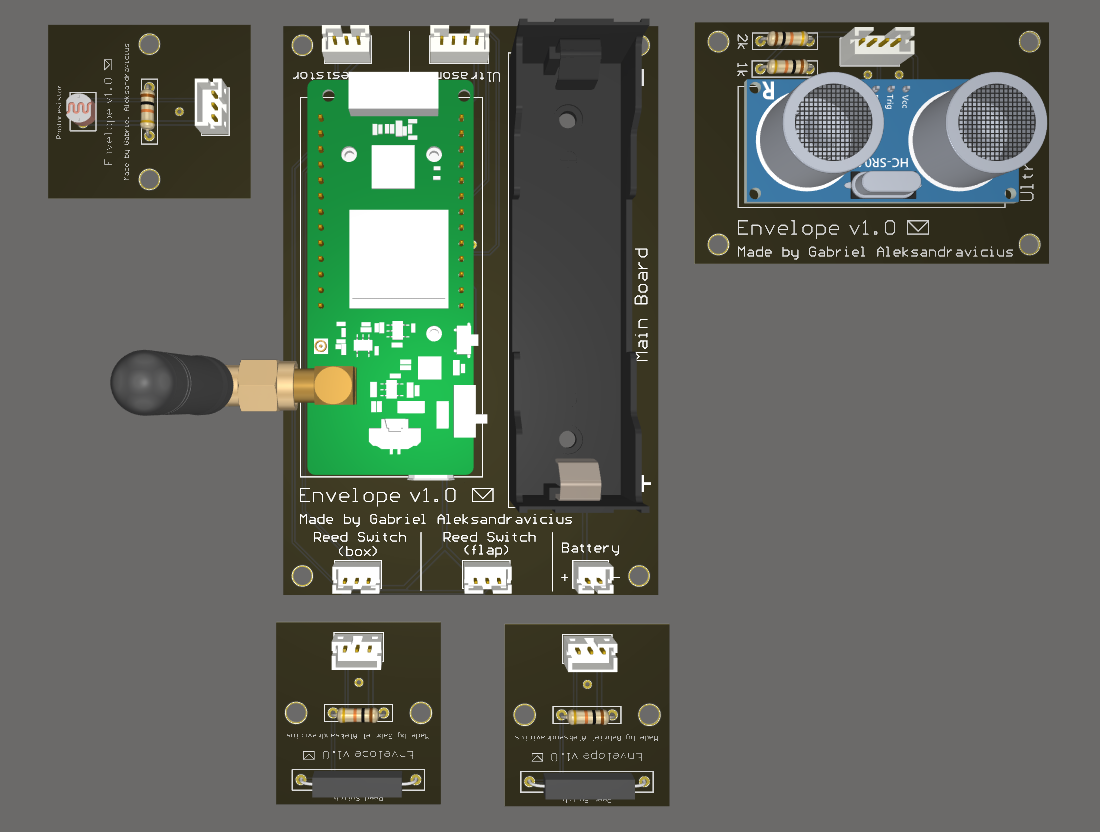
Altium - Multiboard view
Fabricating and soldering the boards #
After finishing with the designs on Altium and running the DRC (Design Rule Check) on each project, I exported the gerber and drill hole files and fabricated them with JLCPCB. Here are the unsoldered boards:
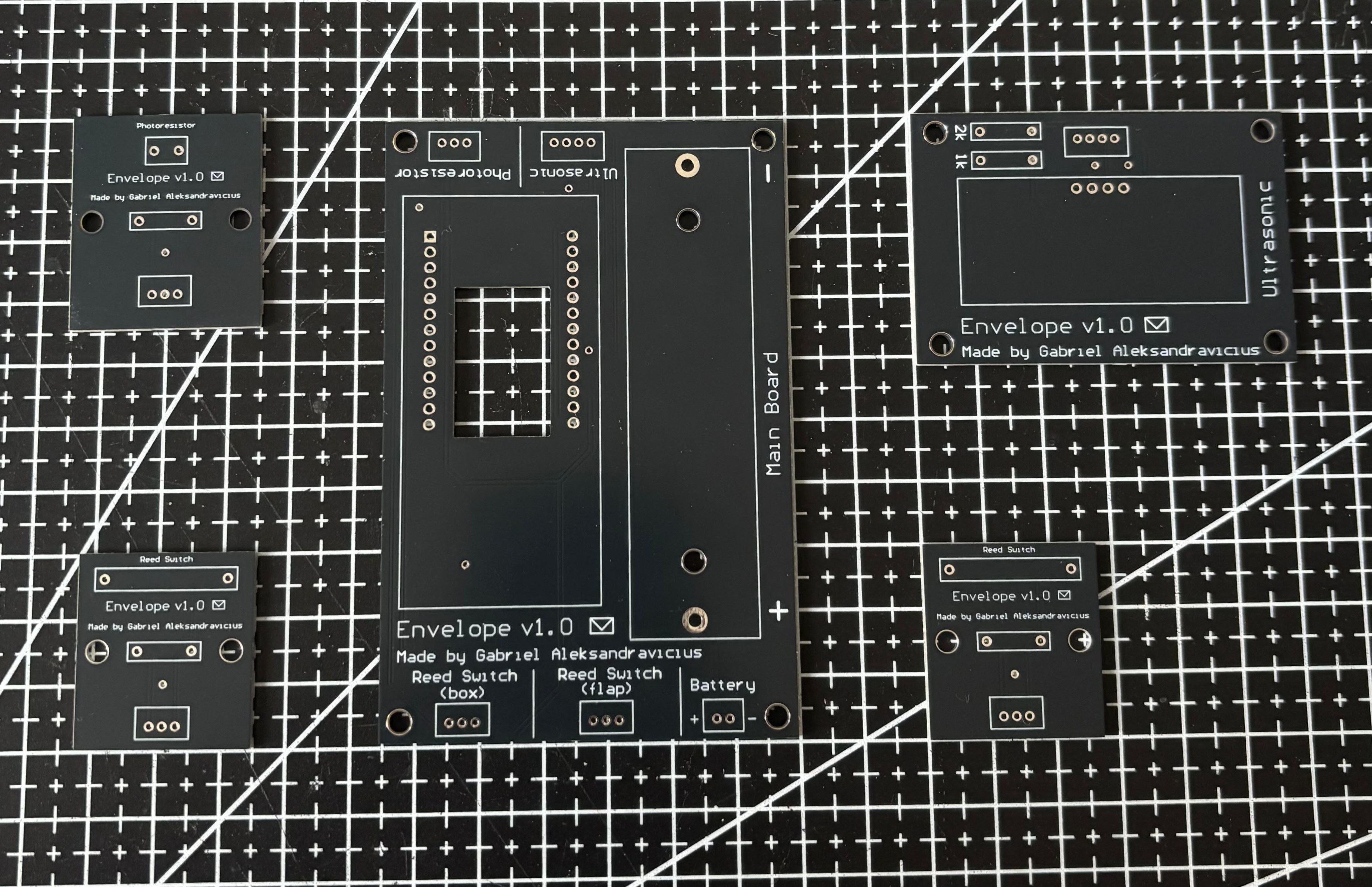
Unsoldered PCBs
And here they are after I soldered everything:
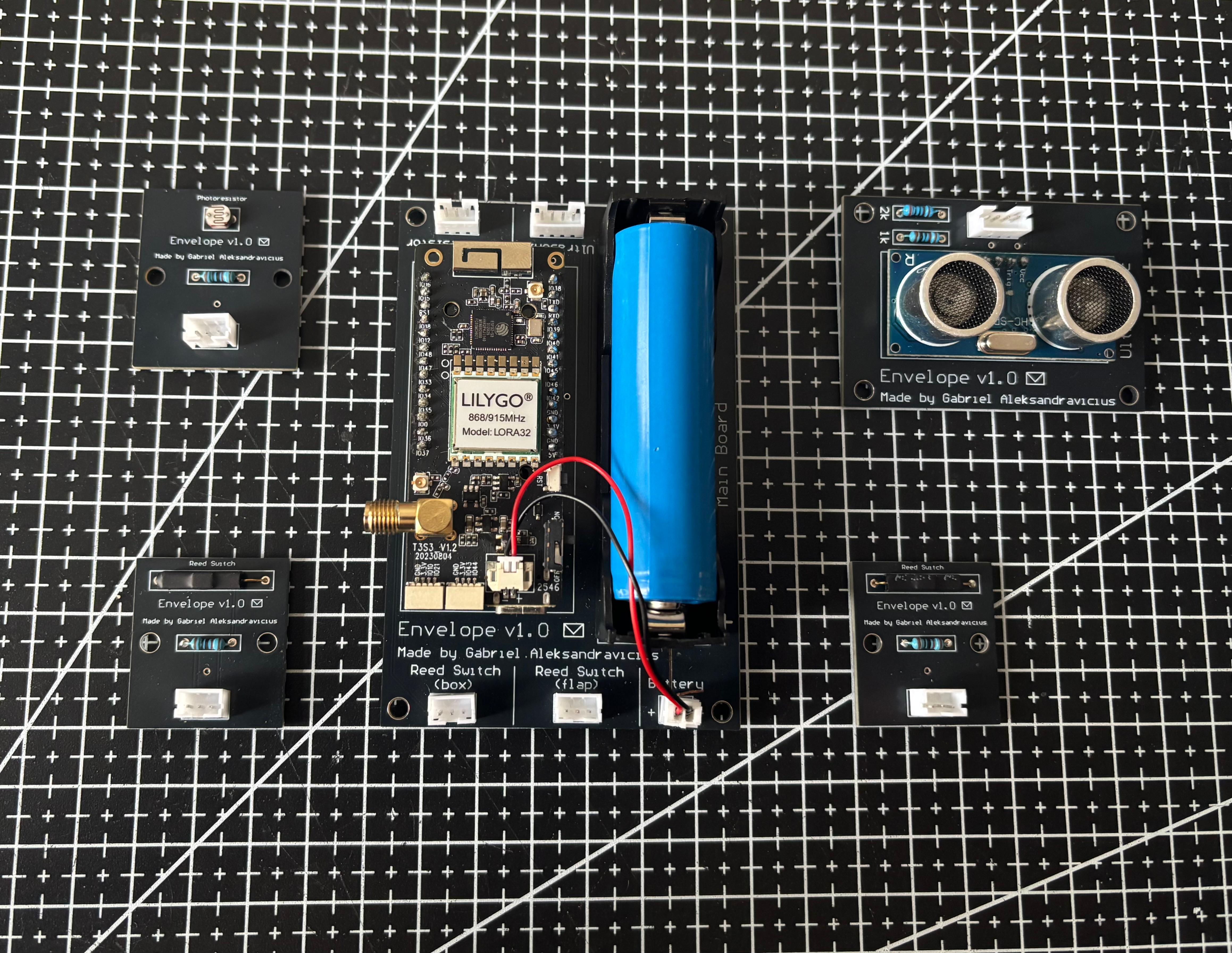
Soldered PCBs
Validating the PCBs #
After crimping the connectors and soldering the components, I validated the system with my multimeter. I first tested the continuity between the boards to make sure that the cables were correctly crimped. One or two were not, so I fixed them and went to the next test. With the battery connected, I validated the power lines to make sure that the appropriate voltages were reaching their corresponding pads.
I noticed that the cutout for the display ended up being a teeny tiny bit offset downwards. This happened because I based this on the 3D model they make available, which apparently isn’t perfect. In any case, this is not a big problem as I can still see the display, but if I ever make a v2, I’ll make sure to update this.
Everything arrived 10 days before the crimp tool… so I ended up crimping the connectors by hand with a set of pliers! At first it was terrible and I lost a bunch of contacts, but eventually I learned how to do it. After the tool arrived, I decided to re-crimp everything and oh man how different the experience became.
The first time I crimped the battery cable, I did it backwards, so when I tested the battery, the trace that leads from the battery holder to the battery connector just… burned. I was honestly expecting something more terrible to happen, so looking at it now this was actually a relief - and also cool, it was the first time I saw a trace burn like that.
Deploying the system #
Installing the transmitter module on the mailbox #
Here’s how the main board looks in its enclosure:
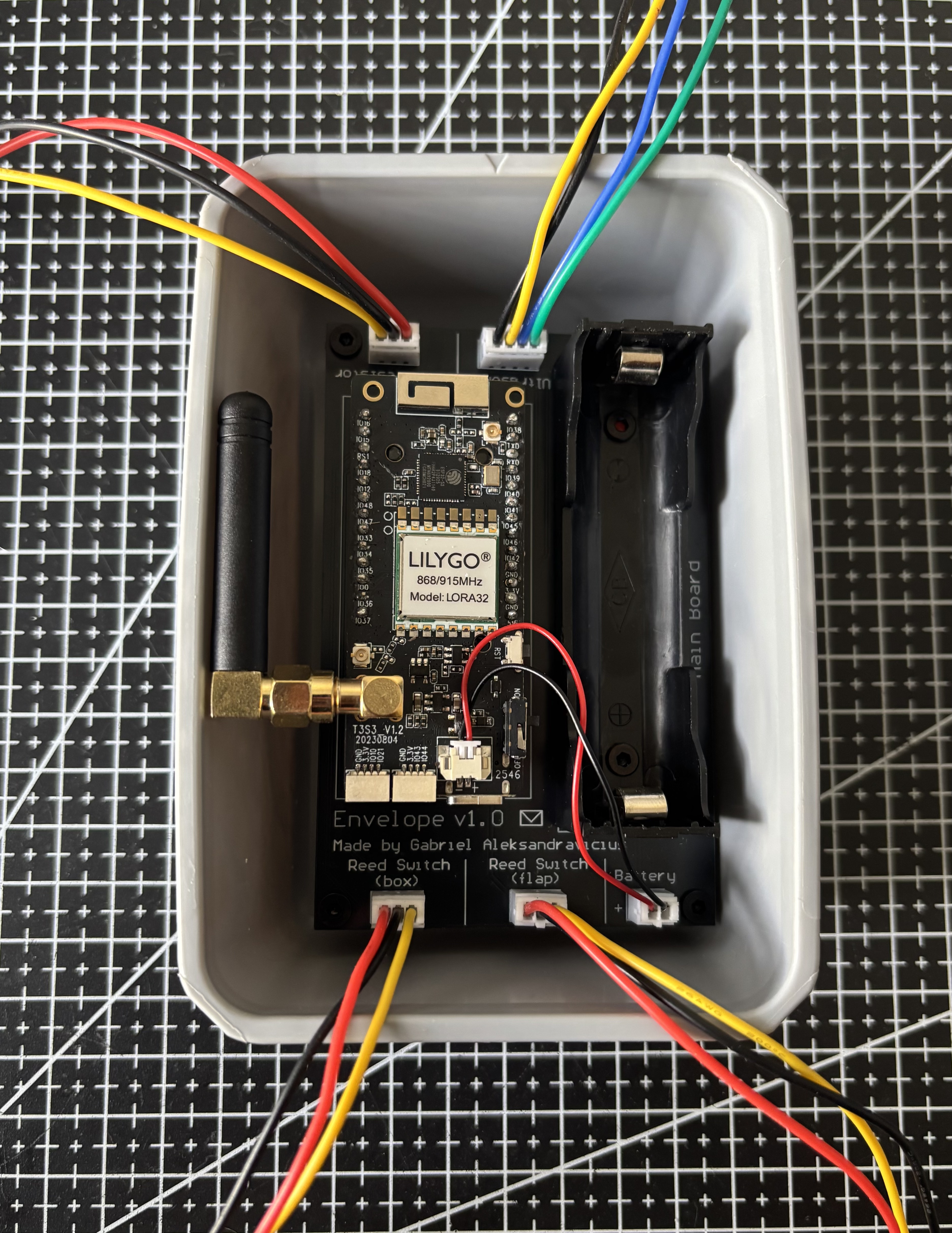
Main board in enclosure
I used small cables to validate the PCBs - around 20cm in length. This was very practical on the test bench since it didn’t occupy much space. For the actual mailbox, though, I had to use longer cables since the components are scattered inside the mailbox and the main board’s enclosure will sit on the bottom-left corner. For example, the photoresistor module is right next to the main board, so I used 20cm cables, but the ultrasonic module was more distant and the reed switches even more - and one is farther than the other. Since I knew the internal compartment size of the mailbox and knew where I wanted each module to be, I chose the length of the cables so each module was reachable, and added an extra margin for safety.
I then brought everything I needed to install the system into the mailbox:
- PCBs
- Battery
- Magnets
- Plastic enclosure
- Cables
- Adhesive-backed cable tie mounts
- Double-sided foam tape
- Cutting pliers
My first task was to find, for each magnet, a spot 2.5cm away where I could safely tape the corresponding reed switch module. I ended up deciding to tape one reed switch on the right side of the mailbox, with its magnet taped directly on the flap; the other reed switch I taped at the ceiling, right next to the door, with its magnet taped right next to it.
I used the bottom parts of the adhesive-backed cable tie mounts as surfaces for the magnets. The magnets were taped to that surface, and that surface was taped to the mailbox.
After validating the reed switch and magnet positions, I proceeded to the final part of the installation: handling cable management. I installed this at night, so thanks Ayumi for holding the flashlight for me while I connected everything!
This was the final result:
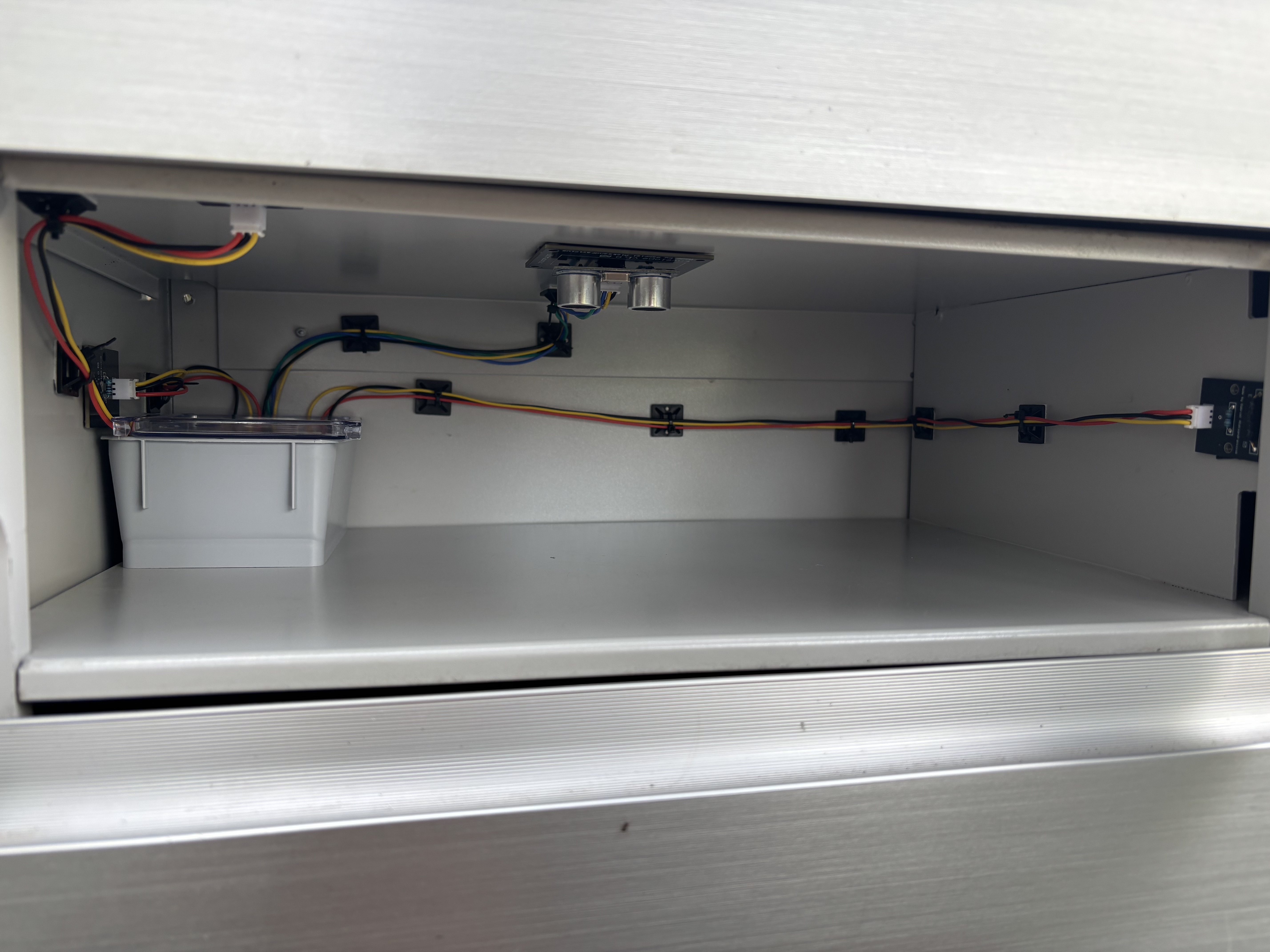
Mailbox with the transmitter module inside
Check the image below to see the positions I chose for the magnets. The magnet on the right is used with the box reed switch, while the one on the left is used for the flap.
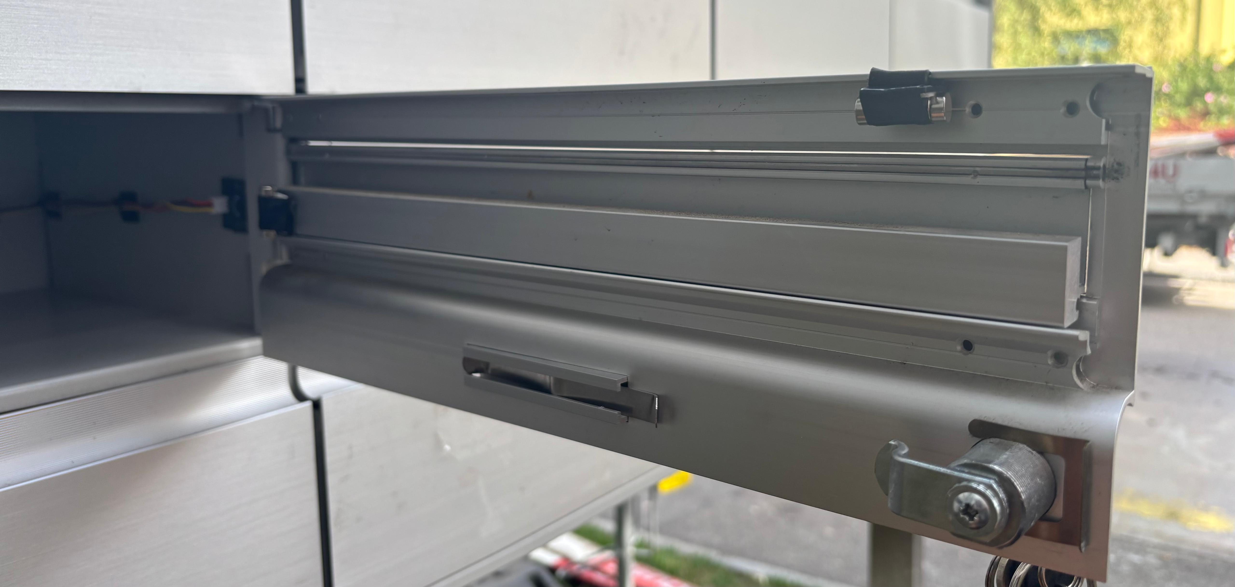
Magnets on the door of the mailbox
Complete view of the system:
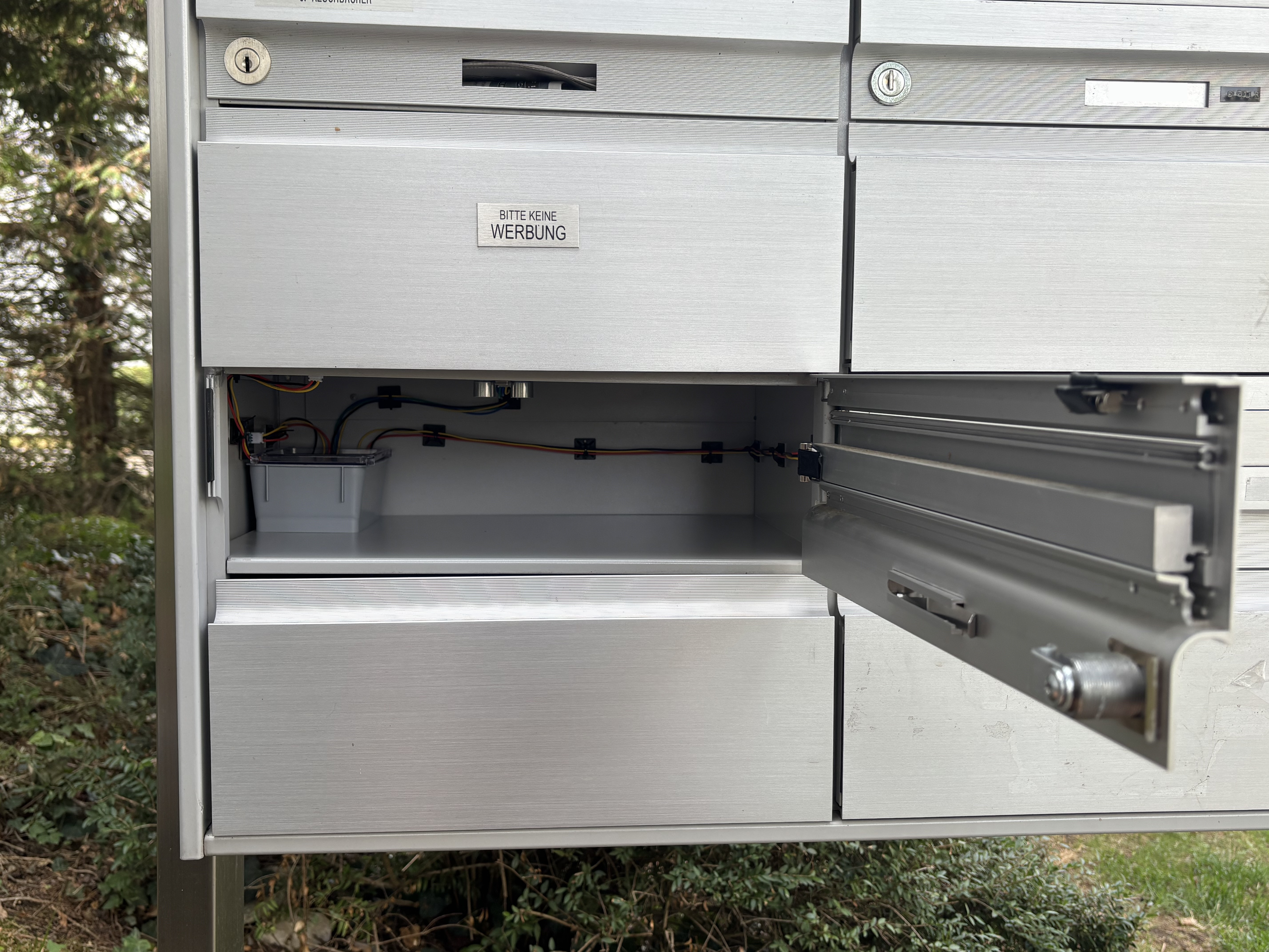
Mailbox with the transmitter module inside and magnets on the door
I am very proud of how this ended up looking! The double-sided tape I bought is amazing - it held the PCBs and the magnets in place very well and even if I use the flap aggressively, putting myself in the shoes of an angry mailman, the components don’t move. I really liked the cable management I did too - the system ended up looking quite elegant in my opinion.
Deploying the Hub on the homelab #
The very final task was to deploy the Hub module on my homelab. So far I’d been using the system with my computer serving the Hub, so the MQTT broker and UI application (with SQLite) were all running on it. Deploying on my homelab meant doing the following:
- Running Mosquitto and the hub app as Docker services on kaos, my homelab Pi, with the same broker credentials and topic setup the firmware already expected.
- Pointing the receiver’s secrets at kaos’s address instead of my computer’s, and reflashing it.
- Setting up a small CI/CD pipeline: GitHub Actions builds the hub app’s Docker image, pushes it to GitHub Container Registry, then deploys it to kaos over an SSH tunnel via Tailscale.
- Making sure the SQLite database persisted on kaos’s filesystem instead of living inside the container, so it survives redeploys.
- Routing the app through Traefik, my existing reverse proxy on kaos, so it’s reachable at
https://envelope.kaoshome.devwith a real TLS certificate instead of a bare IP and port. - Verifying the whole pipeline end-to-end with a real mailbox event.
For a full breakdown of how I add new dockerized services to my homelab, feel free to read my other post: A Repeatable Pattern for Adding New Docker Services Behind Traefik .
Result #
We’re done! Now, I have been validating it >in production< with >real users< (seems funny to call my mailbox and the mailman like that) for the last few days.
Here are two videos I did with the system in action. The first one shows the insertion of mail being registered:
The second one shows the mail collection event being registered:
The system has been working pretty well, with every opening of the flap and box door correctly reported - even if sometimes the type of event is not correct. Check the section below for more details.
Afterthoughts and next steps #
- So far, the most common issue is a wrong type of event being reported. This has to do with the
FILL_DELTA_THRESHOLD_MMI am using. Inserting a single letter isn’t common, but it can happen, and it comes in variants too - sometimes I get ads in the form of fliers or thin sheets of paper. SinceFILL_DELTA_THRESHOLD_MMis (at the time of writing) set to 4, if the mail being inserted is less than 4mm thick, it won’t be identified by the ultrasonic sensor. The obvious fix would be to reduce this threshold or just remove it, but then I may start getting a bunch of false inserts since the sensor is not super precise. I still have to run some tests to see how to proceed. Something I can do is get a bunch of readings from the ultrasonic to get rid of possible noise, but this needs to be executed quickly so as not to disturb the agility of the system. - I enjoyed crimping AWG 26 cables. I had some spare AWG 28 to compare, and indeed using the former offered me an easier experience when learning how to use my crimping tool while still giving me more mechanically robust results than the latter. There was no need for the extra space that the smaller cable would give me.
- I like the off-the-shelf plastic box I bought to serve as the T3-S3’s enclosure, but to make it look nicer, someday I want to 3D print a custom enclosure.
- I haven’t yet measured the continuous draw that my circuit has in deep sleep because of the pull-up resistors (2x10k on the reed switches). Claude calculated that to be a ~660µA continuous draw, dwarfing the deep sleep’s draw (~10-25µA). At that rate, 2200mAh gets me roughly 4-5 months, not “practically forever” as I initially established.
- The battery I bought is listed as having built-in overcharge/overdischarge/short-circuit protection, but its stated length doesn’t match a protected cell (those run a few mm longer to fit the protection PCB), so I’m treating that claim as boilerplate rather than trusting it. I want to add an inline PTC resettable fuse on the battery+ lead as an actual safeguard, sized to hold above normal draw but well below a short-circuit current.
- I also skipped conformal coating on the module PCBs for this first version, even though the mailbox’s sealed-but-humid interior (condensation risk, though no direct water exposure) would benefit from it. Something to revisit if I ever see corrosion.
- Currently, communication is one-way: transmitter -> receiver -> hub. This means that I don’t know if there has been an error on the transmitter unless I go and check. I am planning on adding some type of heartbeat to the system so the transmitter advertises itself as working and, if I miss too many expected heartbeats, the UI should let me know.
- I am considering adding some extra notification to the system, like push notifications or emails.
- I used this as an opportunity to see how to write tests in PlatformIO. Turns out that if the function you want to test lives in a file that has hardware dependencies (e.g., it has
#include <Arduino.h>), the test won’t run while the computer is disconnected from the board - even if the function you’re testing never touches the hardware. This can be cumbersome for small projects - like this - but it has its value when working on bigger projects. For example, I wanted to test the event classification method and, when I originally wrote it, it was part ofManager. Since Manager has hardware dependencies, the test could not run “natively”, without hardware. To make this possible, I had to extract the logic into a separate class, so I createdEventClassifier. This was worth it as it forced me to decouple the orchestrator from the plain business logic that drives event classification. Now, for a bad example: I also wanted to testBattery::getPercentagebut couldn’t because ofBattery::getVoltage, which usesanalogRead()to read from the battery pin. It made no sense for me to extract getPercentage into a different class, so I just decided to not test this at all. In the end, you have to determine what makes sense to you.
That’s it, thank you for reading! I had a lot of fun with this project. Ever since I started my homelab project and this blog, I have been very happy with the personal projects I worked on. Sometimes they take a bit more time than expected to finish - either because I have to focus on my job or because of an unexpected challenge - but I am super happy with this ever-growing environment built for myself. Writing about it here also makes me more self-conscious about the work I do and how I explain/present stuff, so I have been learning a lot not only technically but also from the perspective of a writer!
References #
- HiveMQ - MQTT Essentials: https://www.hivemq.com/blog/mqtt-essentials-part-1-introducing-mqtt/
- Cedalo - How to configure Mosquitto MQTT Broker in Docker: https://www.cedalo.com/blog/mosquitto-docker-configuration-ultimate-guide
- LilyGo - T3-S3 (v1.2): https://lilygo.cc/en-us/products/t3s3-v1-0
- ESPBoards - LilyGo T3S3 (Pinout, Specs and Features): https://www.espboards.dev/esp32/lilygo-t3s3-v1-0/
- Luis Llamas - Measure light level with Arduin and LDR photoresistor: https://www.luisllamas.es/en/measure-light-level-arduino-ldr-photoresistor/
- Luis Llamas - Using a magnetic switch with Arduino (magnetic reed): https://www.luisllamas.es/en/use-magnetic-switch-arduino-magnetic-reed/
- Random Nerd Tutorials - ESP32 with LoRa using Arduino: https://randomnerdtutorials.com/esp32-lora-rfm95-transceiver-arduino-ide/
- Random Nerd Tutorials - ESP32 Deep Sleep with Arduino IDE and Wake-Up Sources: https://randomnerdtutorials.com/esp32-deep-sleep-arduino-ide-wake-up-sources/
- Random Nerd Tutorials - ESP32 Light Sleep Mode and Wake-Up Sources (Arduino IDE): https://randomnerdtutorials.com/esp32-light-sleep-arduino/
- Matt’s Tech Pages - Common JST Connector Types: https://www.mattmillman.com/info/crimpconnectors/common-jst-connector-types/
- Espressif - Watchdogs: https://docs.espressif.com/projects/esp-idf/en/stable/esp32/api-reference/system/wdts.html